Spendor s 35 owners manual

This is the 3 pages manual for spendor s 35 owners manual.
Read or download the pdf for free. If you want to contribute, please upload pdfs to audioservicemanuals.wetransfer.com.

Page: 1 / 3
spendor s 35 owners manual

Extracted text from spendor s 35 owners manual (Ocr-read)


Page 1

Spendor 53/5 Specification

Low/Mid Frequency unit Spendor 130mm Homopolymer Polypropylene
High Frequency unit 19mm Soft Dome

Crossover point 4.5kHz

Nominal Impedance 8 ohms

Frequency response i3dB 80Hz to 20kHz

Pair Matching Within 1dB

Power Handling 70 watts

Sensitivity 84dB/1 watt/1 metre

Maximum SPL 100dBA at 1 metre

Input connections Gold-plated 4mm terminals, Bi-wire option
Cabinet size (HXWXD) 305 x 165 x 180mm (12 x 6.5 x 7 in)
Weight 4.7kg (10.3]b)

Due to a policy of continual development Spendor/Audio Systems United reserves the rigntm make changes Without notice to these specifitations

Loudspeaker Positioning

Spendor 83/5 loudspeakers are designed to be free-standing, in that there should be an air space between the cabinet
and large surface areas (walls and floor). The high frequency unit should be at about ear height for the normal listening
position. If mounted above or below it will be advantageous to tilt them to face the listener.

Where loudspeakers have to be placed near to the corners of a room, they should be positioned non~equidistant from the
side and rear walls. This reduces the effect of the phase differences between the reflections from the two walls and the
directly radiated sound. Most loudspeakers should never be placed tightly into a corner, for although this increases the
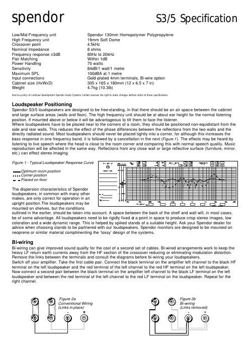
bass response in one frequency band, it is followed by a cancellation in the next (Figure 1). The effects may be heard by
listening to live speech where the head is close to the room corner and comparing this with normal speech quality. Music
reproduction will be affected in the same way. Reflections from any close wall or large reflective surface (furniture, mirror,
etc.) can effect stereo imaging.

Figure 1 - Typical Loudspeaker Response Curve m - .9; at i: an rm (.7. m El El u.- El El
|Il l3 .Mu -.El l3 El E1 ' El lIl lIl

- Optimum room position " -

- - - - Cornerposition

- - Placed on floor

The dispersion characteristics of Spendor
loudspeakers, in common with many other - .
makes, are only correct for operation in an ..

uprightposition.Theloudspeakers may be I ' w.....,l'-'_-, MEI Er l£l iii Elk [5:42.

q

mounted on shelves, but the conditions

outlined in the earlier, should be taken into account. A space between the back of the shelf and wall will, in most cases,
be of some advantage. All loudspeakers need to be rigidly fixed a a point in space to produce crisp stereo images, low
coloration and a wide dynamic range. This is helped by spiked stands of a suitable height. Ask your Spendor dealer for
advice when choosing stands to be partnered with our loudspeakers. Spendor monitors are designed to be mounted on
neoprene or similar material complimenting the lossy design of the systems.

Bi-wiring

Bi-wiring can give improved sound quality for the cost of a second set of cables. Bi-wired arrangements work to keep the
heavy LF return earth currents away from the HF section of the crossover reducing or eliminating modulation distortion.
Remove the links between the terminals and consult the diagrams before bi-wiring your loudspeakers.

Switch off your amplifier. Take the first cable pair. Connect the black terminal on the amplifier left channel to the black HF
terminal on the left loudspeaker and the red terminal of the left channel to the red HF terminal on the left loudspeaker.
Now connect a second pair between the black terminal on the amplifier left channel to the black LF terminal on the left
loudspeaker and between the red terminal of the left channel to the red LF terminal on the loudspeaker. Repeat for the
right channel.


Figure 2a
Conventional Wiring
(Links in place)


- Figure 2b
® Bi-wiring
(Links removed)

Page 2

Queries and Service

If you require advice or service on your audio system please contact your Spendor dealer. We recommend that you retain
all the packaging for your loudspeakers in case you need to transport them safely in the future.

Warranty

All Spendor Classic Series loudspeakers (The Equipment) are guaranteed against defects in components and materials
for a period of 5 years from date of purchase. Within this period parts will be replaced free of charge provided that failure
is not due to accident, negligence or misuse. Labour and carriage are not covered except by local agreement. The
guarantee offered does not affect the consumers statutory rights. To obtain Service under guarantee the equipment
together with an original or clear copy of proof of purchase must be delivered to a local Spendor dealer or distributor at
the owners expense.

Spendor Audio Systems Ltd and any of its authorised distributors or dealers reserve the right to refuse service under
guarantee if the equipment has been subject to unauthorised modification or any of the serial numbers identifying the
equipment have been defaced or removed.

Please register ownership of your Spendor loudspeakers by completing and returning the enclosed registration card.
This will help us to deal quickly with any queries regarding your equipment.

Wiring up

Position your loudspeakers where you want them before wiring up and choose suitable cable runs of approximately equal
length.Switch off your amplifier. Check that the shorting links are in place between the HF and LF terminals of bi-wired
loudspeakers and that the links are in place between the LF, MR and HF terminals on tri~wired models. For information on
bi- and tri-wiring, see your loudspeaker specifications.

Deal with each channel separately. Connect the black terminal (marked negative or with a symbol) on the amplifier left
channel to the black terminal on the left loudspeaker. Similarly, connect the red terminal (marked positive or with a +
symbol) of the left channel to the red terminal on the left loudspeaker. Repeat these connections for the right channel.
Turn the volume control down and switch on the amplifier. Pick a source (CD, Tape etc..) and advance the volume control
carefully.

Cable Quality

Loudspeaker cables can have an important effect on sound quality in the overall context of balancing the complete sound
reproduction system, not just in feeding the correct signal to the speakers but also in affecting the performance of the
amplifier. Advice should be sought from your Spendor dealer. When bi- or tri-wiring you can use different cable types for
the two/three HF/MF/LF sections in both channels. To retain the correct frequency balance of the loudspeaker, cables
should have a loop resistance of less than 0.49. It is recommended that you break and remake loudspeaker connections
periodically to check for poor joints and surface corrosion of the bare cable.

Loudspeaker Power Ratings

For full details regarding the power handling of your Spendor loudspeakers please see your loudspeaker specifications.
Moving coil drive units show two types of permanent damage. Distortion or fracture of the cone/voice coil assemblies
occurs where the cone movement is large enough to deform the material beyond its elastic limit, or damage is caused by
physical contact with the magnet/frame assembly. This occurs mainly in the low frequency range of any specific unit.
Voice coil overheating (burn out) - the more frequent damage - can occur at any frequency but is usually associated with
middle and upper frequencies. These two power limitations may not have the same value.

In most loudspeaker drive units, a large part of the input power is dissipated as heat within the voice coil, The maximum
input power is therefore directly related to the heat energy that the voice coil/magnet assembly can dissipate before the
temperature rises to a point where the coil former or adhesives suffer physical changes and fail. The temperature rise of
the coil is associated both with the power applied and the period of time for which the power is applied.

Where the overload conditions are bounded only by the limits of the cone excursion, the maximum continuous input
power and the maximum peak power, may have the same value.

So for a single drive unit, two values are needed to express the maximum power capabilities in absolute terms - for multi-
driver systems the number of values would, in most cases, be the number of units plus one, to cover the bass limitations.
This means that for a three drive-unit system, such as the Spendor SP1/2, a single value for maximum input power,
continuous or any other time period, cannot be specified. Each unit will have its own rating that is frequency dependent.
Fortunately, for general use - the reproduction of speech and music - the power input to a loudspeaker is constantly
changing. This, coupled with a programme spectrum that normally falls in level at both low and high frequencies, allows a
maximum power rating figure to be given to a system that bears little relationship to the only measurable figure, i.e..
average watts x time.

Analysis of a range of programme material shows large variations, with time, in the relationships between the peak power
values and the RMS or average power values. Percussive instruments, for instance, may have an instantaneous peak-to-
average power ratio of 20 to 1.

The only relevant figure which can be placed on the maximum power input to any system which is to be used for normal
programme material, therefore, is one which takes into account all the factors mentioned. This figure can be termed peak
programme power and is directly related to the maximum power that should be delivered by the driving amplifier. In the
case of the SP1/2E, 100 watts is quoted, and is meant to cover normal programme material that has a spectrum where