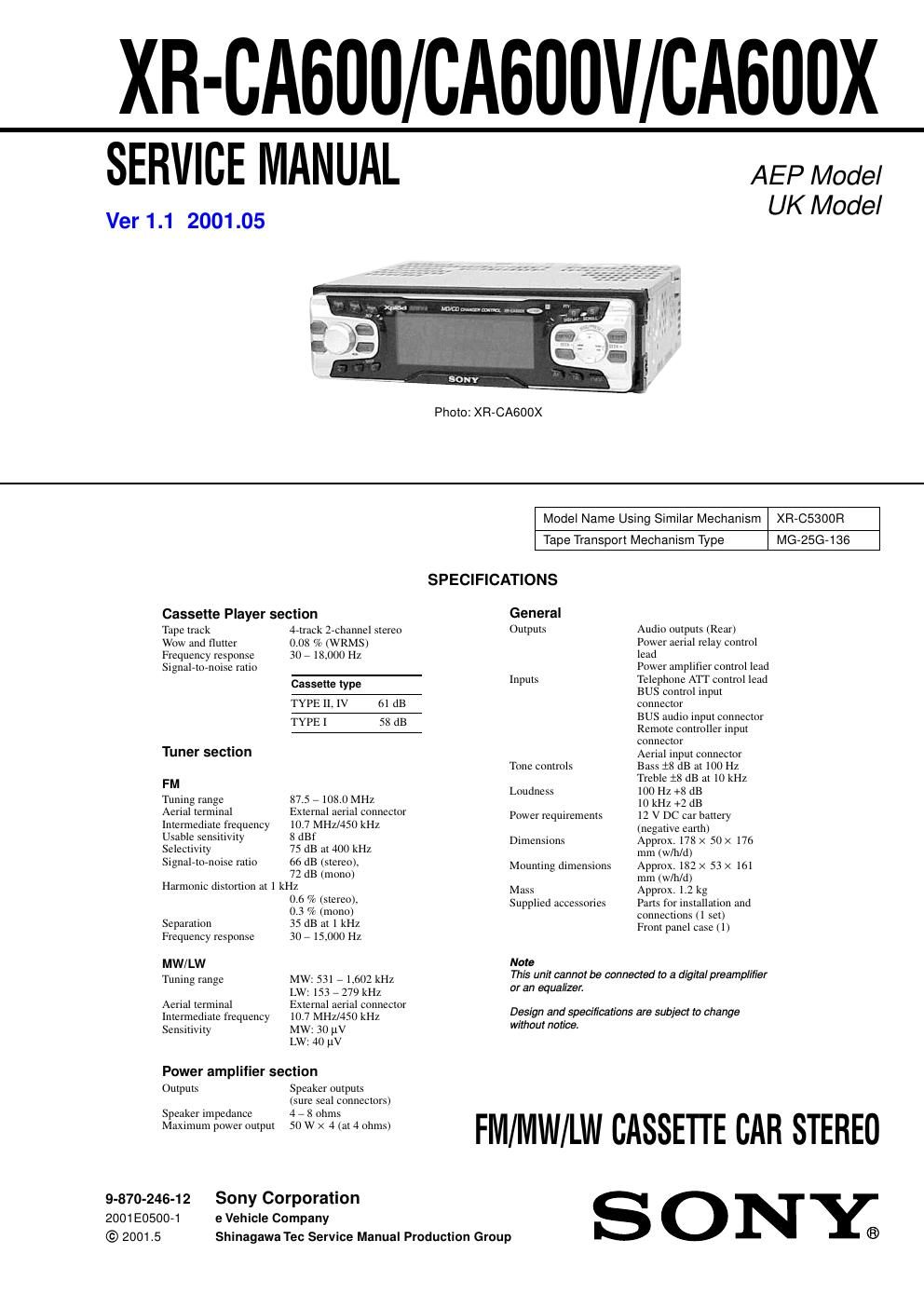
Sony xr ca 600 x service manual
This is the 40 pages manual for sony xr ca 600 x service manual.
Read or download the pdf for free. If you want to contribute, please upload pdfs to audioservicemanuals.wetransfer.com.
Extracted text from sony xr ca 600 x service manual (Ocr-read)
Page 1
2 XR-CA600/CA600V/CA600X TABLE OF CONTENTS 1. GENERAL Location of Controls ....................................................... 3 Setting the Clock ............................................................. 4 2. DISASSEMBLY 2-1. Disassembly Flow ........................................................... 8 2-2. Mechanism Deck (MG-25G-136) ................................... 8 2-3. MAIN Board ................................................................... 9 2-4. Heat Sink (ISO2P) .......................................................... 9 3. ASSEMBLY OF MECHANISM DECK 3-1. Housing ........................................................................... 10 3-2. Arm (Suction) ................................................................. 10 3-3. Lever (LDG-A)/(LDG-B) ............................................... 11 3-4. Gear (LDG-FT) ............................................................... 11 3-5. Guide (C) ......................................................................... 12 3-6. Mounting Position of Capstan/Reel Motor (M901) ....... 12 4. MECHANICAL ADJUSTMENTS ....................... 13 5. ELECTRICAL ADJUSTMENTS Tape Deck Section .......................................................... 13 Tuner Section .................................................................. 13 6. DIAGRAMS 6-1. Note for Printed Wiring Boards and Schematic Diagrams ....................................................... 14 6-2. Printed Wiring Board – MAIN Board –......................... 15 6-3. Schematic Diagram – MAIN Board (1/3) –................... 16 6-4. Schematic Diagram – MAIN Board (2/3) –................... 17 6-5. Schematic Diagram – MAIN Board (3/3) –................... 18 6-6. Printed Wiring Board – SUB Board –............................ 19 6-7. Schematic Diagram – SUB Board –............................... 19 6-8. Printed Wiring Board – KEY Board (XR-CA600/CA600X) –......................... 20 6-9. Printed Wiring Board – KEY Board (XR-CA600V) –...................................... 21 6-10. Schematic Diagram – KEY Board –.............................. 22 6-11. IC Pin Function Description ........................................... 26 7. EXPLODED VIEWS 7-1. General Section ............................................................... 29 7-2. Front Panel Section ......................................................... 30 7-3. Mechanism Deck Section (MG-25G-136) ..................... 31 8. ELECTRICAL PARTS LIST ............................... 32Notes on chip component replacement -Never reuse a disconnected chip component. -Notice that the minus side of a tantalum capacitor may be dam- aged by heat. Flexible Circuit Board Repairing -Keep the temperature of the soldering iron around 270 ˚C dur- ing repairing. -Do not touch the soldering iron on the same conductor of the circuit board (within 3 times). -Be careful not to apply force on the conductor when soldering or unsoldering.
Page 2
3 XR-CA600/CA600V/CA600X SECTION 1 GENERAL This section is extracted from instruction manual. Location of controls Refer to the pages listed for details. : During tape playback : During radio reception : During menu mode : During CD/MD playback (optional) aVolume control dial 13 bMBP button 19 cSOURCE (Power on/Tape/Radio/CD / MD) button 5, 9, 10, 11, 13, 19, 20, 22 dDisplay window eZ (eject) button (located on the front side of the unit, behind the front panel) 9 fReceptor for the card remote commander gMENU button 8, 9, 10, 14, 15, 18, 19, 20, 22, 23, 24 hDISPLAY/PTY (display mode change/ programme type) button12, 15, 21, 22 iSCROLL button 21 jOPEN button 7, 9 k LIST button 11 22, 23 lEQ7 button 19 mRESET button (located on the front side of the unit, behind the front panel) 7nNumber buttons (3) REP 9 10, 11, 13, 14 (3) REP 21 (6) SHUF 21 oMODE (o) button 9 10, 11, 13 20, 22 pSOUND button 17, 19 qAF button 12, 14 rTA b u t t o n 13, 14 sOFF (Stop/Power off) button *5, 7, 9, 20 tENTER button 11, 14 8, 9, 10, 15, 18, 19, 20, 22, 23, 24 22, 23 *Warning when installing in a car without an ACC (accessory) position on the ignition switch After turning off the ignition, be sure to press (OFF) on the unit for 2 seconds to turn off the clock display. Otherwise, the clock display does not turn off and this causes battery drain TAPE RADIO MENU CD/MD 1 2 3 4 5 6 AF TA OFF DS MENU LIST SOUND ENTER MBP SOURCE REP SHUF MODE EQ 7 DISC/PRESET SEEK SEEK DISPLA Y OP E N PTY S C R OLL RADIOCD/MD TA P E RADIOCD/MD TAPERADIOCD/MD RADIOMENU CD/MD . uDISC/PRESET buttons (+/–) 10, 11, 15 8, 9, 10, 14, 15, 18, 19, 20, 22, 23, 24 20, 22, 23 vSEEK buttons (–/+) 9 10, 11, 13 8, 9, 15, 17, 18, 19, 20, 24 20, 22, 23 AF TA OFF DS MENU LIST SOUND ENTER DISC/PRESET SEEK SEEK DISPLAY O PE N SCROLL PTY (SEEK) (–): to select leftwards/ .(SEEK) (+): to select rightwards/ > (DISC /PRESET)/(PRESET) (+): to select upwards In menu mode, the currently selectable button (s) of these four are indicated with a M in the display. (DISC /PRESET)/(PRESET) (–): to select downwards RADIOMENU CD/MD TAPERADIOMENUCD/MD