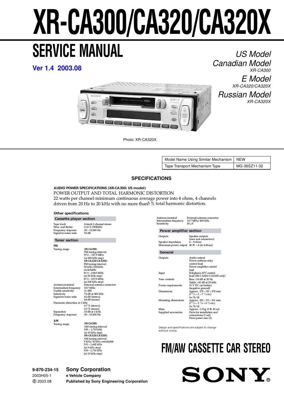
Sony xr ca 320 service manual
This is the 50 pages manual for sony xr ca 320 service manual.
Read or download the pdf for free. If you want to contribute, please upload pdfs to audioservicemanuals.wetransfer.com.
Extracted text from sony xr ca 320 service manual (Ocr-read)
Page 1
2 XR-CA300/CA320/CA320X Flexible Circuit Board Repairing - Keep the temperature of the soldering iron around 270 ˚C dur- ing repairing. - Do not touch the soldering iron on the same conductor of the circuit board (within 3 times). - Be careful not to apply force on the conductor when soldering or unsoldering. Notes on chip component replacement - Never reuse a disconnected chip component. - Notice that the minus side of a tantalum capacitor may be dam- aged by heat. TABLE OF CONTENTS 1. GENERAL Location of Controls ....................................................... 3 Setting the Clock ............................................................. 3 Installation ....................................................................... 4 Connections ..................................................................... 5 2. DISASSEMBLY 2-1. Disassembly Flow ........................................................... 8 2-2. Sub Panel ......................................................................... 8 2-3. Mechanism Deck (MG-36SZ11-32) ............................... 9 2-4. MAIN Board ................................................................... 9 2-5. Heat Sink ......................................................................... 10 2-6. Bracket (MD) .................................................................. 10 2-7. Motor (Capstan/Reel) (M901) ........................................ 11 2-8. Main Belt, Sub Belt (C) .................................................. 11 2-9. Head (Play Back) (HP901) ............................................. 12 3. MECHANICAL ADJUSTMENTS ....................... 13 4. ELECTRICAL ADJUSTMENTS ......................... 13 Tape Deck Section .......................................................... 14 Tuner Section .................................................................. 15 5. DIAGRAMS 5-1. Note for Printed Wiring Boards and Schematic Diagrams ....................................................... 18 5-2. Printed Wiring Board – MAIN Board – ........................ 19 5-3. Schematic Diagram – MAIN Board (1/2) – .................. 20 5-4. Schematic Diagram – MAIN Board (2/2) – .................. 21 5-5. Printed Wiring Board – CONTROL Board – ................ 22 5-6. Schematic Diagram – CONTROL Board – ................... 23 5-7. IC Pin Function Description ........................................... 25 6. EXPLODED VIEWS 6-1. General Section ............................................................... 27 6-2. Front Panel Section ......................................................... 28 6-3. Mechanism Deck Section (MG-36SZ11-32) ................. 29 7. ELECTRICAL PARTS LIST ............................... 30
Page 2
3 XR-CA300/CA320/CA320X SECTION 1 GENERAL This section is extracted from instruction manual. 5 Location of controls RELEASE DIR 6 5 4 3 2 1 B TM DSPL AT T SEEK AMS SENS SELMODE SRC SOURCE D-BASS OFFMBP D DISC REP SHUF ATA Refer to the pages listed for details. 1Volume +/– button 7 2MODE button During radio reception: BAND select 8, 9 During CD/MD playback: CD/MD unit select 12 3SOURCE (TUNER/CD/MD) button 8, 9, 12 4SEL (select) button 7, 10, 11, 12 5Z (eject) button 7, 8, 9, 12 6Display window 7m/M (fast winding)/DIR (tape transport direction change) buttons 7, 8 8MBP (My Best sound Position) button 11 9D-BASS button 11 q;SEEK/AMS +/– button 9, 13 Seek 9 Automatic Music Sensor 13 Manual search 13 qaRELEASE (front panel release) button 6, 14 qsATT (attenuate) button 10 qdSENS button 9qfRESET button (located on the front side of the unit behind the front panel) 6 qgFrequency select switch* (located on the bottom of the unit) See Frequency select switch in the Installation/Connections manual. qhNumber buttons 8, 9, 10, 12, 13 During radio reception: Preset number select 9 During tape playback: (6)ATA 8 During CD/MD playback: (1)DISC – 13 (2)DISC + 13 (3)REP 13 (4)SHUF 13 qjBTM button 8 qkDSPL (display mode change) button 7, 12 qlOFF button** 6 *XR-CA320/CA320X only **Warning when installing in a car without ACC (accessory) position on the ignition key switch Be sure to press (OFF) on the unit for two seconds to turn off the clock display after turning off the engine. When you press (OFF) momentarily, the clock display does not turn off and this causes battery wear. Setting the clock The clock uses a 12-hour digital indication. Example: To set the clock to 10:08 1 Press (DSPL) for two seconds. The hour indication flashes. 1 Press either side of the volume button to set the hour. 2Press (SEL). The minute indication flashes. 3Press either side of the volume button to set the minute. 2 Press (DSPL). The clock starts. After the clock setting is complete, the display returns to normal playback mode. to go forward to go back to go forward to go back