Sony xr c 900 service manual

This is the 63 pages manual for sony xr c 900 service manual.
Read or download the pdf for free. If you want to contribute, please upload pdfs to audioservicemanuals.wetransfer.com.

Page: 1 / 63
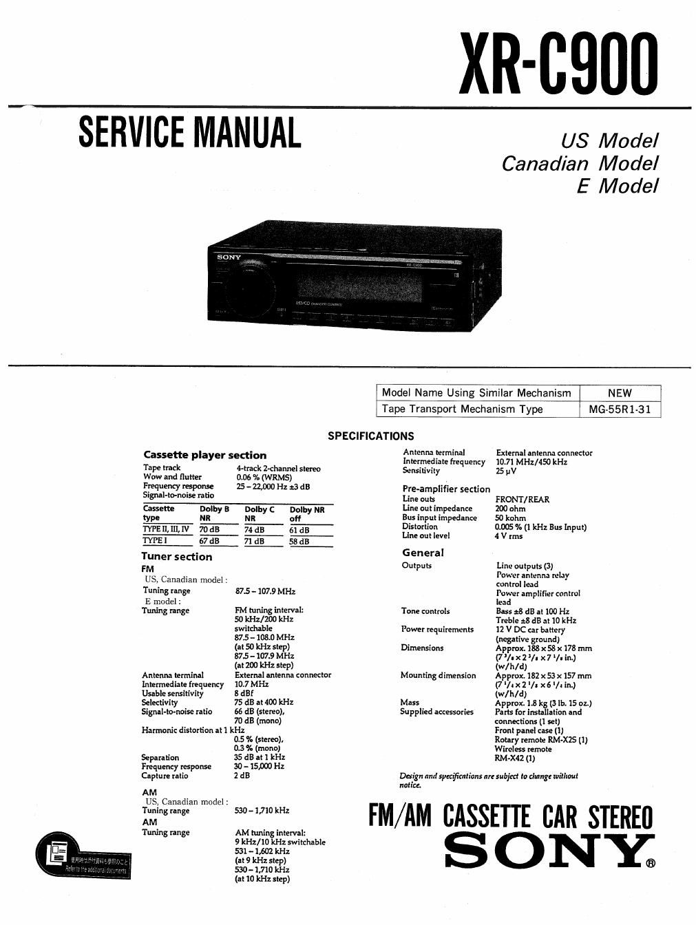
sony xr c 900 service manual

Extracted text from sony xr c 900 service manual (Ocr-read)


Page 1

XR-CQDU

SERVICE MANUAL

US Model
Canadian Model
E Model

Model Name Using Similar Mechanism NEW

Tape Transport Mechanism Type MG55R1-31

SPECIFICATIONS

Cassette player section

Antenna terminal

External antenna connector

Intermediate Frequency 10.7l MHz/450 kHz
Tape track 4-track Z-channel stereo Sensitivity 25 "V
Wow and flutter 0.06 % (WRMS) .
Frequentyresponse 2542.000 Hz dds Pre-amplifier section
S'Wl'm'm' "5° Line outs FRONT/REAR
Cassette Dolby a Dolby c Dolby Mn Line out impedance 200 ohm
type NR NR off Bus Input impedance 50 kohrn
W 70T W m- Distortion 0.005% (1 kHz Bus input)
TYPE i 67 dB 71 dB 53 dB I'm I level 4 V ""s
Tuner section General
FM Outputs Line outputs (3)
. Power antenna relaV
US Canadian model : '
_ control lend
Tuning range 87.5 -107.9 MHz Power amplifier control
E model : lead
Tuning range FM tuning interval: Tone controls Bass :8 dB at 100 Hz
50 kHz/ZOO kHz Treble :8 dB at 10 kHz
switchable Power requirements 12 V DC car battery
87.5 -- 10M) MHz (negative ground)
(at 50 kHz step) Dimensions Approx. 188 x 58 x 178 mm
87.5 ~ 107.9 MHz (7 l- x2 '/a x 7 I- in.)
(at 200 kHz step) (w/h/d)
Antenna terminal External antenna connector Mounting dimension Approx. 182 x 53 x 157 mm
Intermediate frequency 10.7 MHz (7 v. x 2 l/. x 6 v. in.)
Usable sensitivity 8 dBf (w/ h/ d )
Selectivity 75 dB at 400 kHz Mass Approx. 1.8 kg (3 lb. 15 oz.)
Signal-tortoise ratio 66 dB (stereo), Supplied accessories Parts for instillation and
70 d3 (mono) connections (I set)
Harmonic distortion at 1 kHz Front panel use (1)
0.5 9% (stereo), Rotary remote RM~X2$ (I)
0.3 % (mono) Wireless remote
Separation 35 dB at 1 kHz RM-X42 Cl)
Frequency response 30- 15.000 Hz
Capture ratio 2 dB Dolgn and spen'firntions or: subjtct to change without
notice.
AM
US, Canadian model :
Tuning range 5304.710 kHz FM AM CASSETTE c A
AM
Tuning range AM tuning interval:
9 kHz/ 10 kHz switchable
531 - 1,602 kHz
(at 9 kHz step) ®
530 - 1,710 kHz

(3! 10 kHz step)

Page 2

TABLE OF CONTENTS


1. GENERAL 3-12. Reverse Arm (M) ........... 1 ................... 26
Location of controls ................................ 3 3-13. Rotary Slide Switch . . . . .26
Getting Started ............................... 4 3-14. MD Cover . . . . .27
Cassette Player ............................... . .5 3-15. EQ Board . . . . . . .27
Radio ...................................... . . .6 3-16. Housing Hanger . . . . .28
Other Functions ............................. .. .7 3-17. Hanger Bracket Sub Assy .28
CD/MD Changer . .8 3-18. Buffer Spring ........... . .29
DSP ........ . . . . 3-19. Suction Arm Assy ....... 29
TV/Video .

Connections 4. MECHANICAL ADJUSTM ENTS .................. 30

2. DISASSEMBLY 5. ELECTRICAL ADJUSTMENTS

2-1. Front Panel .................................... 16 Deck Section ...................................... 30

2-2. MD Block ....................... 16 Tuner Section ...................... . . .31

2-3. Heat Sink ....................... 17

2-4. Panel (Base) ....................... 17 6. DIAGRAMS

2-5. Motor Block ....................... 18 6-1. IC Pin Descriptions .............................. 34

2-6. Sub Panel ........................... 18 62. Circuit Boards Location ........................ 38

2-7. Main Board ......................... 19 6-3. Printed Wiring Boards-Main Sectioni .......... 40

2-8. Key Board ...................................... 19 6-4. Schematic DiagramAMain Section- ............ 45

6-5. Printed Wiring BoardePanel Section- .......... 50

3. ASSEMBLY OF MECHANISM DECK 6-6. Schematic Diagram-Panel Section? ............ 52

3-1. FR Gear Assy .. .. ..

3-2. Arm Assy ............................. 20 7. EXPLODED VIEWS

3-3. Head Base Assy . . . . ......................... 21 7.1. Cover Section ,.

3-4. RVS Lever Assy . . . . ......................... 22 7-2. Front Panel Section ............................ 60

35. Midway Pulley (P) ............................. 22 7-3. Chassis Section .................................. 61

3-6. Capstan Motor ................................ 23 7-4. Mechanism Deck Section (1) .................... 62

3-7. Tension Spring . . ............................. 23 7-5. Mechanism Deck Section (2) .................... 63

3-8. Flywheel ..................................... 24 7-6. Mehcanism Deck Section (3) .................... 64

3-9. Mode Arm Assy ................................ 24 7-7. Mechanism Deck Section (4) .................... 65

3-10. Pinch Arm Assy .. ..................... 25

3-11. MCU PC Board Sub Assy ........................ 25 8. ELECTRICAL PARTS LIST ...................... 66

Dolby noise reduction manufactured under license from Dolby Labora- Notes on Chip Component Replacement

tories Licensing Corporation.
DOLBY and the double-D symbol DD are trademarks of Dolby Labora-
tories Licensing Corporation.

- Never reuse a disconnected chip component,
- Notice that the minus side of a tantalum capacitor may be
damaged by heat.