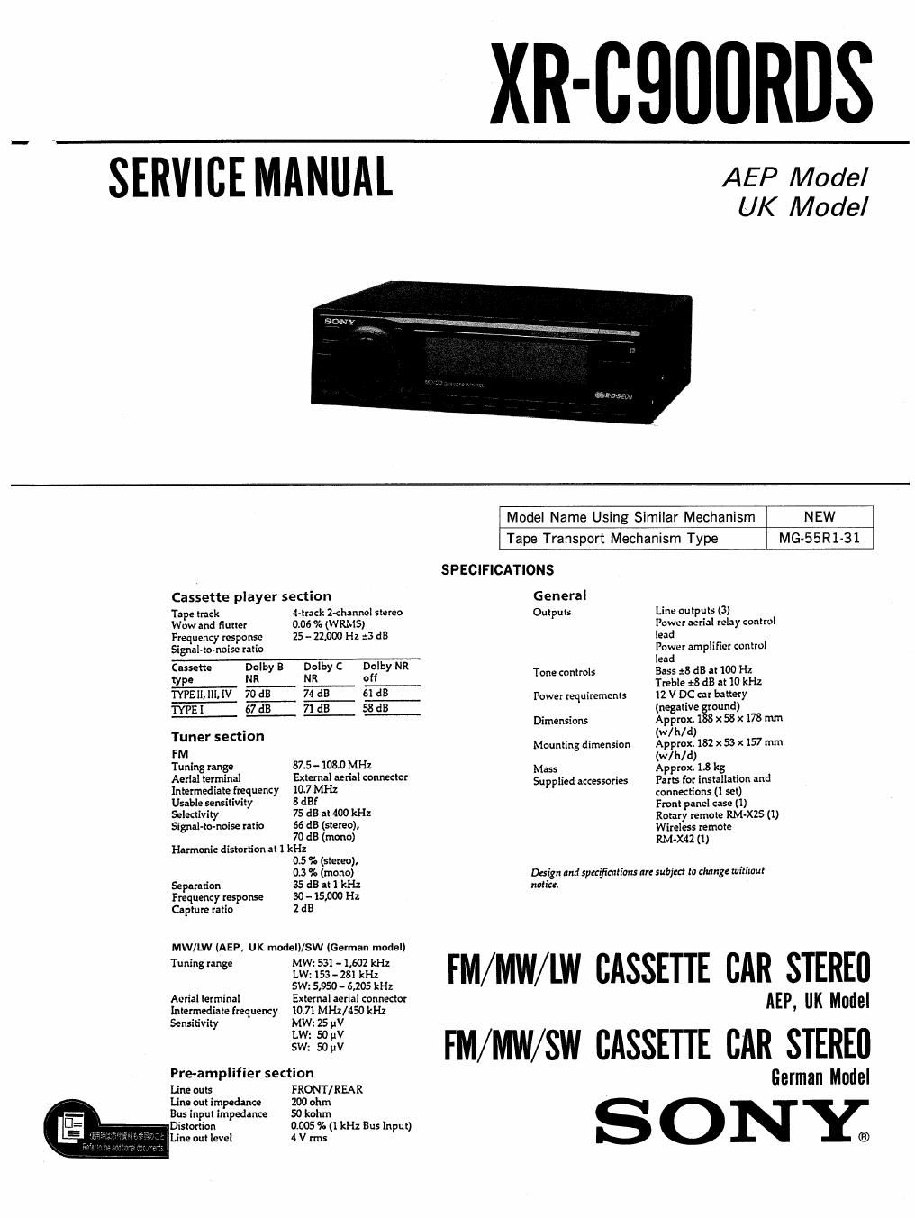
Sony xr c 900 rds service manual
This is the 62 pages manual for sony xr c 900 rds service manual.
Read or download the pdf for free. If you want to contribute, please upload pdfs to audioservicemanuals.wetransfer.com.
Extracted text from sony xr c 900 rds service manual (Ocr-read)
Page 2
1.
2.
2-1.
2-2.
2-3.
2-4.
2-5.
2-6.
2-7.
2-8.
3.
3-1.
3-2.
3-3.
3-4.
3-5.
3-6.
3-7.
3-8.
39,
3-10.
3-11.
TABLE OF CONTENTS
GENERAL
Location of controls . . .
Getting Started .......
Cassette Player . ..
Radio .............
RDS
ther Functions .....
CD/MD Changer . ..
DSP ........... ;
Connections
DISASSEMBLY
Front Panel
MD Block ........
Heat Sink ........
Panel (Base) ......
Motor Block ........
Sub Panel ..........
Main Board
Key Board . . . .
ASSEMBLY OF MECHANISM DECK
FR Gear Assy .................................. 21
Arm Assy ............................... 21
Head Base Assy . . . . ..................... 22
RVS Lever Assy ......................... 23
Midway Pulley (P) . . .. ................... 23
Capstan Motor ........................... 24
Tension Spring ........ . . .24
Flywheel .............. . .25
Mode Arm Assy .. .. .25
Pinch Arm Assy ......................... 26
MCU PC Board Sub Assy ........................ 26
Dolby noise reduction manufactured under license from Dolby Labora-
tories Licensing Corporation.
"DOLBY" and the double-D symbol DU are trademarks of Dolby Labora-
tories Licensing Corporation.
3-12. Reverse Arm (M) ................................ 27
3-13. Rotary Slide Switch . . .27
3-14. MD Cover ............................. , . .28
3-15. EQ Board ............................. . . .28
3-16. Housing Hanger ....................... . . .29
3-17. Hanger Bracket Sub Assy . . .29
3-18. Buffer Spring . .30
3-19. Suction Arm Assy .............................. 30
4. MECHANICAL ADJUSTMENTS .................. 31
5. ELECTRICAL ADJUSTMENTS
6.
6-1.
6-2.
6-3.
6-4.
6-5.
6-6.
7.
7-1.
7-2.
7-3.
7-4.
7-5.
7-6.
7-7.
8.
Deck Section .............................
Tuner Section
DIAGRAMS
IC Pin Description .....................
Circuit Boards Location
Printed Wiring Board57Main Sectionv .
Schematic Diagram-Main Section-
Printed Wiring Board-Panel Section! .
Schematic DiagramiPanel Section? ............ 52
EXPLODED VIEWS
Cover Section
Front Panel Section
Chassis Section ...............
Mechanism Deck Section (1)
Mechanism Deck Section (2)
Mehcam'sm Deck Section (3)
Mechanism Deck Section (4)
ELECTRICAL PARTS LIST
Notes on Chip Component Replacement
-, Never reuse a disconnected chip component.
- Notice that the minus side of a tantalum capacitor may be
damaged by heat,
*2-