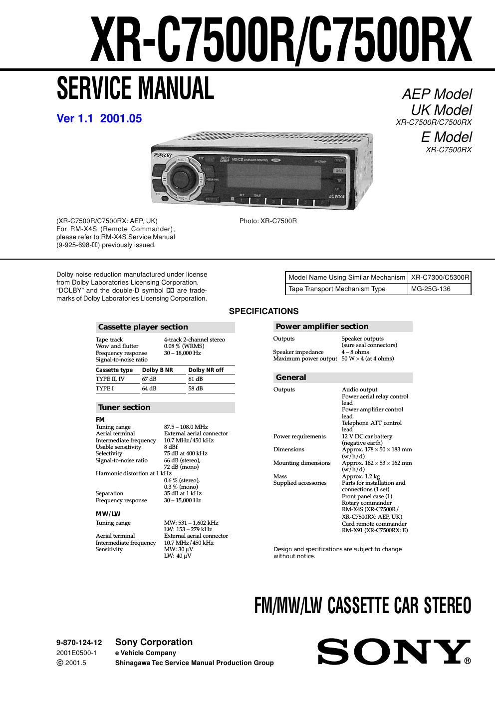
Sony xr c 7500 rx service manual
This is the 54 pages manual for sony xr c 7500 rx service manual.
Read or download the pdf for free. If you want to contribute, please upload pdfs to audioservicemanuals.wetransfer.com.
Extracted text from sony xr c 7500 rx service manual (Ocr-read)
Page 1
2 TABLE OF CONTENTS 1. SERVICING NOTES ............................................... 2 2. GENERAL Location of Controls ....................................................... 3 Setting the Clock ............................................................. 3 Installation ....................................................................... 4 Connections ..................................................................... 6 3. DISASSEMBLY ......................................................... 10 4. ASSEMBLY OF MECHANISM DECK ........... 12 5. MECHANICAL ADJUSTMENTS ....................... 15 6. ELECTRICAL ADJUSTMENTS Test Mode ........................................................................ 15 Tape Deck Section .......................................................... 16 Tuner Section .................................................................. 16 7. DIAGRAMS 7-1. Block Diagram – TUNER/TAPE Section – ................... 17 7-2. Block Diagram – MAIN Section – ................................. 18 7-3. Block Diagram – DISPLAY/KEY CONTROL Section – ........................ 19 7-4. Block Diagram – BUS CONTROL/POWER SUPPLY Section – ........... 20 7-5. Note for Printed Wiring Boards and Schematic Diagrams ....................................................... 21 7-6. Printed Wiring Board – Main Board (Component Side) – ................................ 22 7-7. Printed Wiring Board – Main Board (Conductor Side) – .................................. 23 7-8. Schematic Diagram – Main Board (1/4) – ..................... 24 7-9. Schematic Diagram – Main Board (2/4) – ..................... 25 7-10. Schematic Diagram – Main Board (3/4) – ..................... 26 7-11. Schematic Diagram – Main Board (4/4) – ..................... 27 7-12. Printed Wiring Board – SUB Board – ........................... 28 7-13. Schematic Diagram – SUB Board – ............................... 28 7-14. Printed Wiring Board – KEY Board – ........................... 30 7-15. Schematic Diagram – KEY Board – .............................. 31 7-16. IC Pin Function Description ........................................... 34 8. EXPLODED VIEWS ................................................ 40 9. ELECTRICAL PARTS LIST ............................... 43 Notes on chip component replacement - Never reuse a disconnected chip component. - Notice that the minus side of a tantalum capacitor may be dam- aged by heat. Flexible Circuit Board Repairing - Keep the temperature of the soldering iron around 270 ˚C dur- ing repairing. - Do not touch the soldering iron on the same conductor of the circuit board (within 3 times). - Be careful not to apply force on the conductor when soldering or unsoldering. SECTION 1 SERVICING NOTES MODEL IDENTIFICATION The XR-C7500R and XR-C7500RX have three types of MAIN boards respectively. TUX1 R606R607 CN201 – MAIN BOARD (Conductor Side) – TYPE A TYPE B TYPE C R606×aa R607a×a
Page 2
3 SECTION 2 GENERAL This section is extracted from instruction manual. 5 Location of controls 1MENU button 9, 11, 12, 13, 15, 17, 18, 20, 21, 23, 24, 26, 27, 30, 31, 33, 34, 35 2Volume control dial 3SOURCE (TUNER/TAPE/CD/MD) button 6, 8, 10, 12, 13, 19, 20, 24, 25, 26, 27, 31, 34 4PRST/DISC +/– (cursor up/down) buttons 8, 9, 11, 12, 13, 15, 17, 18, 19, 20, 21, 22, 23, 24, 26, 27, 30, 31, 32, 33, 34, 35 During radio reception: Preset stations select 13 During CD/MD playback: Disc change 32 5DSPL/PTY (display mode change/ programme type) button 11, 18, 23, 31, 33 6LIST button Disc memo 33 List-up 22, 34 7Display window 8 Z (eject) button (located on the front side of the unit behind the front panel) 10 9OPEN button 7, 10, 36 q;DSO button 26 qaSOUND button 24, 25, 26 qsOFF button* 6, 7, 8, 10 qdReset button (located on the front side of the unit behind the front panel) 7 qfSEEK/AMS –/+ (cursor left/right) buttons 8, 9, 10, 11, 12, 13, 15, 17, 18, 19, 21, 23, 24, 25, 26, 27, 30, 31, 32, 33, 35 Seek 13, 15, 19 Automatic Music Sensor 10, 32 Manual search 13, 32 XR-C7500RX/XR-C7500R DISC+PRST+ DISC– PRST- SOURCE DSPL LIST AF OFF PTY ENTER MENU SOUND 1 2 3 4 56 -SEEK/AMS REP SHUF TA OPEN MODE DSO qgENTER button 9, 11, 12, 13, 15, 17, 18, 20, 21, 22, 23, 24, 26, 27, 30, 31, 33, 34, 35 qhMODE button 10, 11, 12, 13, 19, 20, 31, 34 During tape playback: Playback direction change 10 During radio reception: BAND select 12, 13 During CD/MD playback: CD/MD unit select 31 qjReceptor for the card remote commander qkNumber buttons During radio reception: Preset number select 12, 13, 16, 17, 20, 21 During tape playback: (1)REP 11 During CD/MD playback: (1)REP 32 (2)SHUF 32 qlAF button 15, 17 w;TA button 16, 17 *Warning when installing in a car without ACC (accessory) position on the ignition key switch Be sure to press (OFF) on the unit for two seconds to turn off the clock display after turning off the engine. When you press (OFF) only momentarily, the clock display does not turn off and this causes battery wear. Refer to the pages listed for details. 2 Press (ENTER). The clock starts. After the clock setting is complete, the display returns to normal playback mode. Tips - You can use the convenient CT function to set the clock automatically (page 18). - When the D.Info mode is set to on, the time is always displayed (page 30). Setting the clock The clock uses a 24-hour digital indication. Example: To set the clock to 10:08 1 Press (MENU), then press either side of (PRST/DISC) repeatedly until Clock appears. 1 Press (ENTER). The hour indication flashes. 2 Press either side of (PRST/DISC) to set the hour. 3 Press (+) side of (SEEK/AMS). The minute indication flashes. 4 Press either side of (PRST/DISC) to set the minute. A unit turned off by pressing (OFF) for two seconds cannot be operated with the card remote commander unless (SOURCE) on the unit is pressed or a casette is inserted to activate the unit first. Card remote commander RM-X91 The corresponding buttons of the card remote commander control the same functions as those on this unit. 1OFF button 2MENU button 3SOURCE button 4SEEK/AMS (cursor ,) buttons 5SOUND button 6DSPL/PTY button 7ATT button 8LIST button 9DISC/PRST (cursor M/m) buttons q;ENTER button qaMODE button qsVOL buttons OFF SEEK SEEK OPEN/CLOSE MENU LIST SOUND ENTER DISCDISC SOURCE DSPL MODE VO L AT T (XR-C7500RX: E)