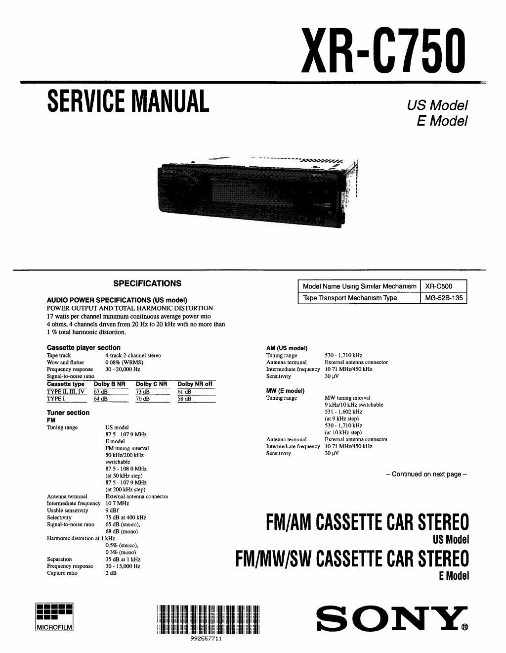
Sony xr c 750 service manual
This is the 42 pages manual for sony xr c 750 service manual.
Read or download the pdf for free. If you want to contribute, please upload pdfs to audioservicemanuals.wetransfer.com.
Extracted text from sony xr c 750 service manual (Ocr-read)
Page 2
SW1, 2 (E model)
'nrning range
Antenna terminal
Intermediate frequency
Sensitivity
SW] r 2,940 - 7,735 kHz
SW2 . 9,500 - 18,135 kHz
(except (0110.140 - 11,575
kHz)
External antenna connector
10 71 MHZI450 kHz
50 W
Power amplifier sectlon
Outputs
Speaker impedance
Speaker outputs
(sure seal connectors)
4 » 8 ohms
Maximum power output 40 W x 4 (at 4 ohms)
General
Outputs
Tone controls
Power requirements
Dimensions
Mounting dimensions
Mus
Supplied accessories
Design and specification: are subject to Change Without
name
Notes on Chip Component Replacement
0 Never reuse a disconnected chip component.
0 Notice that the minus side of a tantalum capacitor may be dam-
aged by heat.
US model -
35w><4 (atAMb-nd,4
ohms)
E model .
35 WX4(utMW uudSW
hind. 4 ohms)
Line outputs (3)
Power Interim rel-y
control lead
Power Imphfier control
lead
Bass : 8 dB at too Hz
Treble 2 8 dB at lOkHz
12 v DC car battery
(negative earth)
Approx.184 x 50x 176 nun
(7 ll4x2x67/Iin)
(w/h/d)
Approx 182x53x163mm
(7 me llsxfimm)
(w/hld)
Approx 13kg(zlb. 1401)
Pam for Installation and
connections (I set)
Front panel one (1)
Rotary remote RM-XZS (I)
Wireless remote
RM-x4s (1) (E model)
TABLE OF CONTENTS
1. GENERAL
Location of Controls.
Setting the Clock ..
Cassette Player ..
Radio ............
Other Functions .
CD/MD Changer
Additional Information
Connections ............
wcqmbwwu
2. DISASSEMBLY
2-1. Cover Assy
2-2. Front Panel Assy ..
2-3. Sub Panel Assy
2-4. Mechanism Deck Block ..
2-5. Heat Sink .........................
2-6. Main Board .............................
3. ASSEMBLY OF MECHANISM DECK
Alignment of Rotary Swttch ..
Gear (LDG-E). ..
Chassis (S) Assy
Lever (Mode) ............
Lever (Pinch Selection)
Head Plate Assy
Lever (Pinch) Assy
Housing .....
Arm (Suction)
Lever (LDG-A)/(LDG»B) .
Gear (LDG-FT) .
Guide (C) .......
4. MECHANICAL ADJUSTMENTS .............................. 22
5. ELECTRICAL ADJUSTMENTS
Deck Section lllll
Tuner Section .....
6. DIAGRAMS
6-1. IC Pin Descriptions... .
62. Block Diagram -TC Section
6'3. Block Diagram -Maih Section-.
6-4. Printed Wiring Boards -Mam Section~
6-5. Schematic Diagram -Main Section:
6-6. Printed Wiring Boards -Pane1 Section-
6-7. Schematic Diagram -Panel Section- .
26
29
3 I
33
37
7. EXPLODED VIEWS
7-1. Chassis Section .t
7-2. Front Panel Section ..
7-3. Mechanism Deck Section-1
7-4. Mechanism Deck Section-2
51
52
. 53
......... 54
8. ELECTRICAL PARTS LIST ...................................... 55
Dolby nolse reductlon manufactured under license from Dolby Labora-
torles Licensing Corporation.
DOLBY and the double-D symbol m are trademarks of Dolby Labora-
tories Licensmg Corporation.
-2-