Sony xr c 503 service manual

This is the 46 pages manual for sony xr c 503 service manual.
Read or download the pdf for free. If you want to contribute, please upload pdfs to audioservicemanuals.wetransfer.com.

Page: 1 / 46
sony xr c 503 service manual

Extracted text from sony xr c 503 service manual (Ocr-read)


Page 1

xn-c503 w

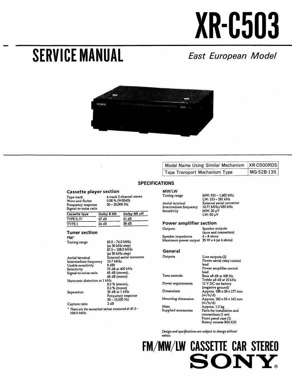
SERVICE MANUAL East European Model

Model Name Using Similar Mechanism XR-CSOORDS
Tape Transport Mechanism Type MG-523-135

SPECIFICATIONS

Cassette player section MW/LW
Tape track Huck 2-channel stereo Tuning range MW: 531 -- 1.602 kHz
Wow and flutter 0.03 °/. (WRMS) . . LW: 153 - 22?! kHz
Frequency response 30 _ 20 Hz Aerial terminal External aerial connector
Signal-to-noise ratio Intermediate frequency 10.71 MHz/450 kHz
...._-..--- Se 'ti t MW: V
Cassette type Dolby 3 NR Dolby NR aft 5' V y LW15300pI-II
TYPE II, IV 67 dB 61 dB
mgr.- L L Power amplifier section
. Outputs Speaker outputs
Tuner section (sure seal connectors)
FM" Speaker impedance _4 - 8 ohms
Tuning range 65.0 _ 74.0 MHZ Maximum power output 35 W x 4 (at 4 ohms)
(at 30 kHz stepéz
37.5 - 108.0 M
(at 50 kHz step) General
Aerial terminal External aerial connector OufPu'S Line outputs (2)
Intermediate frequency 10.7 MHz POW" «rial relay control
Usable sensitivity 9 :13! lead
Selectivity 75 dB at 400 kHz Power amplifier control
Signal-lanoise ratio 65 dB (stereo)y lead
68 dB (mono) Tone controls Bass :8 dB at 100 Hz
Harmonic distortion at 1 kHz Treble :8 dB at 10 kHz
05 % (stereo), Power requirements 12 V DC car battery
0.3 % (mono) . . (negative ground)
Separation 35 dB at 1 kHz Dimensions Approx. 188 x 58 x177 mm
Frequency response . (w/h/d)
30 -15)000 Hz Mounting dimension Approx. 132 x 53 x162 mm
Capture ratio 2 :13 M (W/ h/ d) 3
e - _ 355 Approx. 1. kg
131:; Mfr-[Ira Hurlimm WW" "W's"d " 575 Supplied accessories Parts for installation and
connections (1 set)

Front panel case (1)
Rotary remote RM-XZS

Dlsign and spmficntians are subject to change without
notice.

FM/MW/LW CASSETTE CAR STEREO
S 0 NY;

Page 2

1.

2.

2-1.
2-2.
2-3.
2-4.
2-5.
2-6.

3.

3-1.
3-2.
3-3.
3-4.
3-5.
3-6.
3-7.
3-8.

TABLE OF CONTENTS

GENERAL

Location of controls ..
Getting Started ......
Cassette Player ......


Radio ................

Other Functions ......

CD/ MD Changer . .7

Connections ..................

DISASSEMBLY
Cover ................. . .11
Front Panel Assy ......... .11 '
Sub Panel ................. .12
Heat Sink ................. . . 12
Mechanism Deck Block ..... . .13
Main Board ............... . .13

ASSEMBLY OF MECHANISM DECK
Alignment of Rotary Switch .................... 14
Gear (LDG-E) . . .14
Chassis (S) Assy ............... . . .15
Lever (Mode) ......................... . . .15
Lever (Pinch Selection) ............... . . .16
Head Plate Assy ....................... . .16

. r .17
Housing ........................................ 17

Lever (Pinch) Assy .....................

Notes on Chip Component Replacement

- Never reuse a disconnected chip component,

' Notice that the minus side of a tantalum capacitor may be
damaged by heat.

_2_

3-9.

3-10.
3-11.
3-12.

4.

5.

6.

6-1.
6-2.
6-3.
6-4.
6-5.
6-6.

7.

7-1.
7-2.
7-3.
7-4.

8.

Arm (Suction) .................................. 18

Lever (LDG-B) ..... . . .18

Gear (LDG-FT) ..... . . .19

Guide (C) ...................................... 19
MECHANICAL ADJUSTMENTS .................. 20
ELECTRICAL ADJUSTMENTS

Deck Section ...........
Tuner Section .........

DIAGRAMS
IC Pin Description .....
Block Diagram .......
Printed Wiring Boards-Main Sectioni .
Schematic DiagramMain Section-
Printed Wiring Board-Panel Section- .
Schematic Diagram-Panel Section- ............ 45

EXPLODED VIEWS
Chassis Section .................................. 51
Front Panel Section
Mechanism Deck Section 1 .
Mechanism Deck Section 2 . . .


ELECTRICAL PARTS LIST ...................... 55

Dolby noise reduction manufactured under license from Dolby Labora-
tories Licensing Corporation.
"DOLBY" and the double-D symbol DD are trademarks of Dolby Labora-
tories Licensing Corporation.