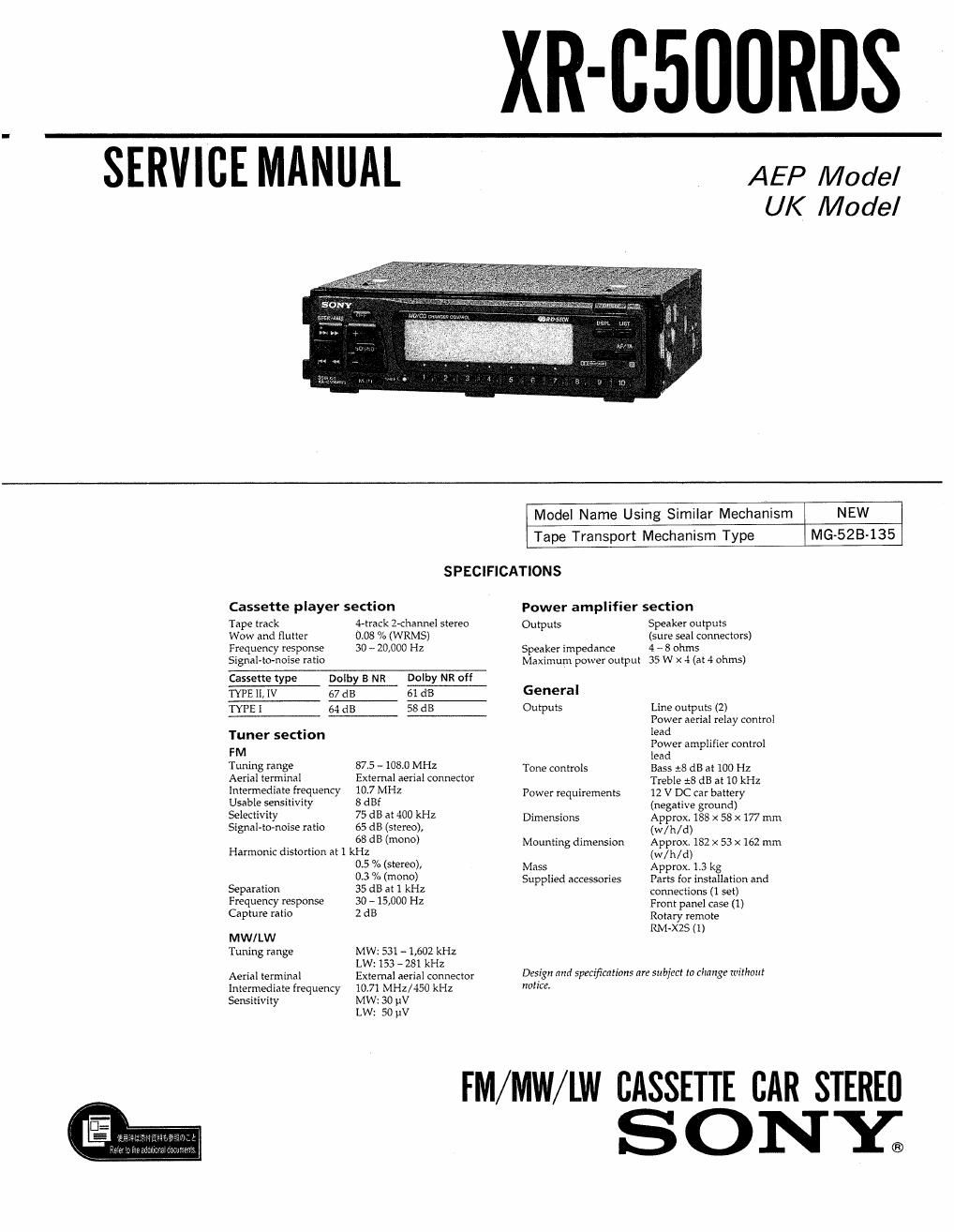
Sony xr c 500 rds service manual
This is the 62 pages manual for sony xr c 500 rds service manual.
Read or download the pdf for free. If you want to contribute, please upload pdfs to audioservicemanuals.wetransfer.com.
Extracted text from sony xr c 500 rds service manual (Ocr-read)
Page 2
TABLE OF CONTENTS
1. GENERAL
Location of controls .............................. 3
Getting Started ..........................
Cassette Player .,
Radio ...........
RDS i i . . ......
Other Functions .........
CD/ MD Changer ........ . .8
Additional Information ............... 10
Connections ...................................... 11
2. DISASSEMBLY
2-1. Cover .......................................... 13
2-2. Front Panel Assy ........................... 13
23. Sub Panel ................................. 14
2-4. Heat Sink ................................. 14
2-5. Mechanism Deck Block. ................ 15
245. Main Board .................................. 15
3. ASSEMBLY OF MECHANISM DECK
3-1, Alignment of Rotary Switch ................... 16
321 Gear (LDG-E) .................................. 16
3-11 Chassis (S) Assy . . . .................... 17
3-4. Lever (Mode) ........................... 17
3-5. Lever (Pinch Selection) .......................... 18
3-6. Head Plate Assy ................................ 18
3-7. Lever (Pinch) Assy ............................ 19
3-8. Housing ................................. 19
Notes on Chip Component Replacement
' Never reuse a disconnected chip component.
- Notice that the minus side of a tantalum capacitor may
be damaged by heat.
3-9. Arm (Suction) . ...................... 20
3-10. Lever (LDC-B) .................... 20
3»11. Gear (LDG-FT) .......... . .21
3-12. Guide (C) ...................................... 21
4. MECHANICAL ADJUSTMENTS .................. 22
5. ELECTRICAL ADJUSTMENTS
Deck Section ...................................... 22
Tuner Section
6. DIAGRAMS
6-1, IC Pin Descriptions .............................. 27
6-21 Block Diagram .................................. 31
6-3. Printed Wiring Boards-Main Sectioni .......... 36
6-4. Schematic DiagramAMain Section- ............ 41
65. Printed Wiring Boarnganel Section- .......... 46
6-6. Schematic Diagram-Panel Sectioni ............ 48
7. EXPLODED VIEWS
7»1. Chassis Section .........................
7-2. Front Panel Section ........
7-3. Mechanism Deck Section 1 ..
7-4. Mechanism Deck Section 2 ..............
8. ELECTRICAL PARTS LIST ...................... 59
Dolby noise reduction manufactured under license from Dolby Labora-
tories Licensing Corporation.
DOLBY" and the doubleD symbol DI] are trademarks of Dolby Labora-
tories Licensing Corporation.