Sony xr c 420 rv service manual

This is the 43 pages manual for sony xr c 420 rv service manual.
Read or download the pdf for free. If you want to contribute, please upload pdfs to audioservicemanuals.wetransfer.com.

Page: 1 / 43
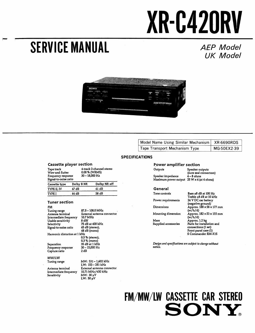
sony xr c 420 rv service manual

Extracted text from sony xr c 420 rv service manual (Ocr-read)


Page 1

XR-C420RV

SERVICE MANUAL

AEP Model
UK Model

vmmflmwum

Cassette player section
Tape track 4-track Z-channel stereo
Wow and flutter 0.08 l. (W RMS)

Frequency response 30 - 18,000 Hz
Signal-tomoise ratio

Cassette type Dolby 5 NR Dolby NR off

TYPE fl. IV 67 dB 61 dB
ME I - 64 dB 58 dB
Tuner section
FM
Tuning range 87.5 -108.0 MHz
Antenna terminal External antenna connector
Intermediate frequency 10.7 MHz
Usable sensitivity 8 dB!
Selectivity 75 dB at 400 kHz
Signal-tomoise ratio 65 d3 (stereo),
: 68 dB (mono)

Harmonie distortion at 1 kHz

0.5 36 (stereo).

0.3 38 (mono)
Separation 35 dB at l kHz
Frequenty response 30 - 15,000 Hz
Capture ratio 2 dB
MW/LW
Tuning range MW: 531 - 1,602 kHz

LW: 153 - 281 kHz
Antenna terminal External antenna eonneetor
Intermediate frequency l0.7t MHz/450 kHz
Sensitivity MW: 30 V

LW: 50 pV

Model Name Using Similar Mechanism XR-6690RDS

Tape Transport Mechanism Type MG-50EX2-39
SPECIFICATIONS
Bower amplifier section
Outpus Speaker outputs
(sure seal connectors)

Speaker impedance 4 - 8 ohms
Maximum power output 5 W x4 (at 4 ohms)

General

Tone controls Bass :8 dB at 100 Hz
Treble 23 dB at 10 kHz

Power requirements 24 V DC at battery
(negative ground)

Dimensions Approx. 188 x 58 x 177 mm
(W/h/d)

Mounting dimension Approx. 182 x 53 x 155 mm
(W/h/d)

Mass Approx. 1.2 kg

Supplied accessories Parts for imballation and

connections (l set)
Front panel ease (l)
5 Commander RM-XlS

Design and specifications are subjert to clung: without
notice.

FM/MW/LW CASSETIE CAR STERED
S ON Y®

Page 2

CAUTIO N
Danger of explosion if battery is incorrectly replaced.
Replace only with the same or equivalent type
recommended by the equipment manufacturer.
Discard used batteries according to manufactuxes

instructions.

ADVARSEL!
Lithiumbatteri - Eksplosionsfare ved fejlagtig handtering.
Udskiftning ma kun ska med batteri
af samme fabrikat 03 type.

Lever det brugte batteri tilbage til leverandoren.

ADVARSEL
Eksplosjonsfare ved feilaktig skifte av batteri.
Benytt samme batteritype eller en tilsvarende
type anbefalt av apparatfabrikanten.
Brukte batterier kasserea i henhold til fabrikantens
instruksjoner.

VARNING
Explosionsfara vid felaktigt batteribyte.
Anvind samma batterityp eller en likvirdig typ som
rekommenderas av apparattillverkaren.
Kassera anvint batteri enligt gallande foreskrifter.

VAROITUS
Paristo voi rajamss, jos se on virheellisesti asennettu.
Vaihda. paristo ainoastaan laitevalmistajan suosittelemaan

tyyppiin.
mukaisesti.

H'a'viti kiytetty paristo valmistajan ohjeiden

Dolby noise reduction manufactured under license from Dolby Labora
tories Licensing Corporationi
DOLBY" and the double-D symbol DI] are trademarks of Dolby Labora
tories Licensing Corporation,

Notes on Chip Component Replacement

~ Never reuse a disconnected chip component.

- Notice that the minus side of a tantalum capacitor may
be damaged by heat

2.

2-1.
2-2.
2-3
2-4.

3.

3-1.
3-2.
33.
3-4.
35.
3-6.
3-7,

6.

6-1.
6-2.
6-3.
6-4.
6-5.
6-6.
6-7.

7.

7-1.
7-2.
7-3.

8.

TABLE OF CONTENTS

GENERAL
Location of controls ................................ 3
Getting Started ............
Cassette Player ............
Radio ......................
RDS
Other Functions ..................
CD Changer ......................
Additional Information
Connections ......................

eagaassa

DISASSEMBLY
Sub Panel ...................................... 11
MD Block ..................... 11
Heat Sink ..................... . . .12
Main Board .................................... 12

ASSEMBLY OF MECHANISM DECK
Installing the Loading Gears
Installing the Reel Bracket ..... . .
Installing the Mode Lever and Pinch Levers ......

Installing the Cassette Housing .................. 15
Installing the Loading Lever .15
Positioning the Loading Levers .. . . i , .16
Installing the Gear (Loading F) .................. 16
MECHANICAL ADJUSTMENTS .................. 17
ELECTRICAL ADJUSTMENTS
Deck Section ..................... .17
Tuner Section .18

DIAGRAMS

IC Pin Descriptions .........
Circuit Boards Location
Block Diagram .........................
Printed Wiring Boards-Main Section-
Schematic Diagram-Main Section»
Printed Wiring BoardiPanel Section- .
Schematic Diagram-Panel Section- iiiii


EXPLODED VIEWS

Chassis Section iiiiiiiiiii . . , .46
Front Panel Section , i47
Mechanism Deck Section ........................ 48
ELECTRICAL PARTS LIST ...................... 49