Sony xr c 4100 service manual

This is the 35 pages manual for sony xr c 4100 service manual.
Read or download the pdf for free. If you want to contribute, please upload pdfs to audioservicemanuals.wetransfer.com.

Page: 1 / 35
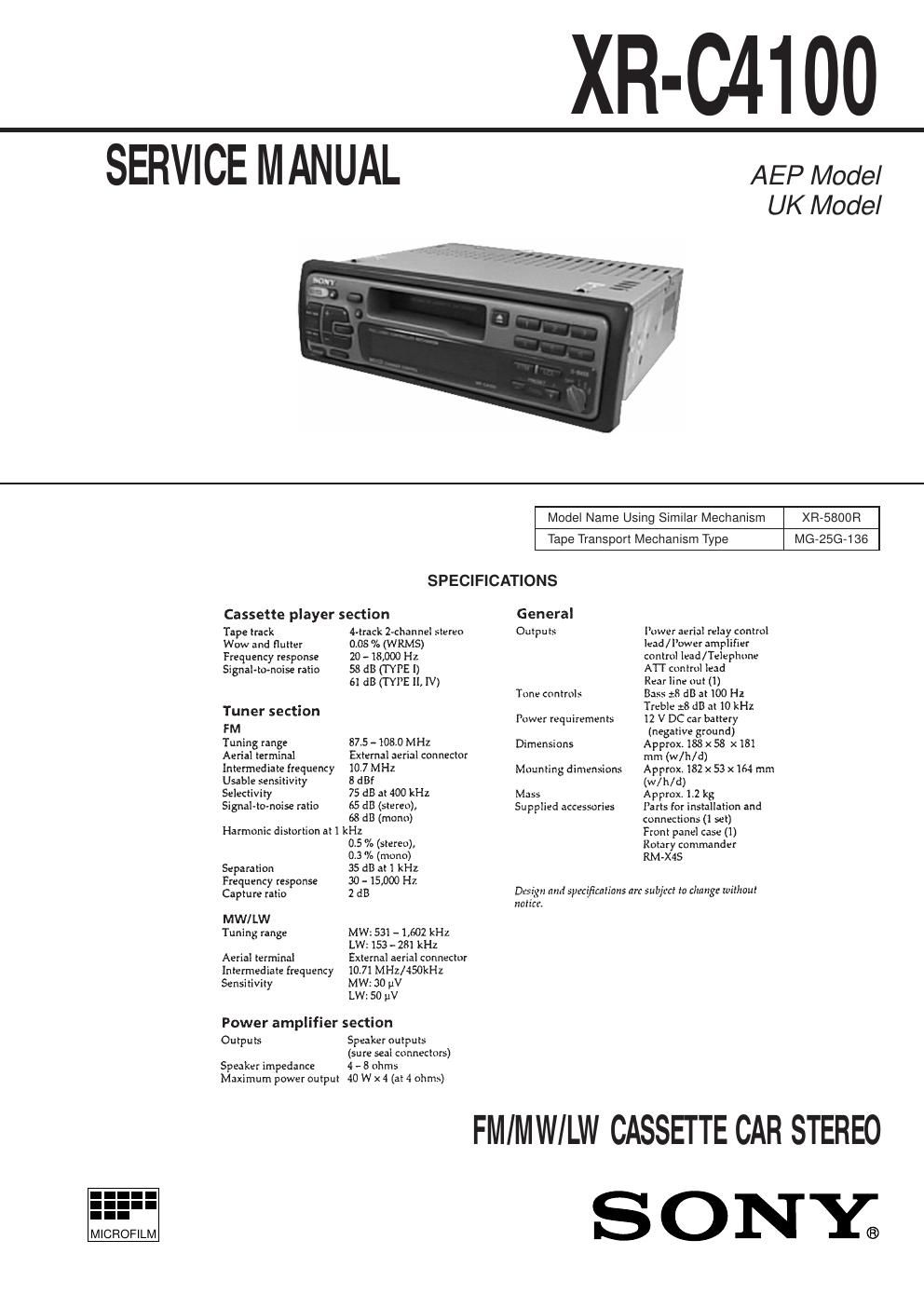
sony xr c 4100 service manual

Extracted text from sony xr c 4100 service manual (Ocr-read)


Page 1

Ð 2 Ð TABLE OF CONTENTS 1. GENERAL Location of Controls ....................................................... 3 Resetting the Unit ........................................................... 4 Detaching the Front Panel ............................................... 4 Preparing the Rotary Commander .................................. 4 Setting the Clock ............................................................. 4 Installation ....................................................................... 5 Connections ..................................................................... 6 2. DISASSEMBLY ......................................................... 9 3. ASSEMBLY OF MECHANISM DECK ........... 11 4. MECHANICAL ADJUSTMENTS ....................... 14 5. ELECTRICAL ADJUSTMENTS Test Mode ........................................................................ 14 Tape Deck Section .......................................................... 14 Tuner Section .................................................................. 15 6. DIAGRAMS 6-1. IC Pin Function Description ........................................... 18 6-2. Printed Wiring Boards ÐMAIN SectionÐ ....................... 21 6-3. Schematic Diagram ÐMAIN SectionÐ ........................... 25 6-4. Printed Wiring Board ÐPANEL SectionÐ ...................... 29 6-5. Schematic Diagram ÐPANEL SectionÐ ......................... 31 7. EXPLODED VIEWS ................................................ 35 8. ELECTRICAL PARTS LIST ............................... 38Flexible Circuit Board Repairing ·Keep the temperature of the soldering iron around 270 û C dur- ing repairing. ·Do not touch the soldering iron on the same conductor of the circuit board (within 3 times). ·Be careful not to apply force on the conductor when soldering or unsoldering Notes on chip component replacement ·Never reuse a disconnected chip component. ·Notice that the minus side of a tantalum capacitor may be dam- aged by heat.

Page 2

Ð 3 Ð SECTION 1 GENERAL This section is extracted from instruction manual.