Sony xr c 400 service manual

This is the 40 pages manual for sony xr c 400 service manual.
Read or download the pdf for free. If you want to contribute, please upload pdfs to audioservicemanuals.wetransfer.com.

Page: 1 / 40
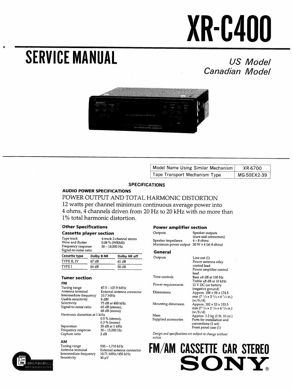
sony xr c 400 service manual

Extracted text from sony xr c 400 service manual (Ocr-read)


Page 1

XR-C400

SERVICEMANUAL

US Model
Canadian Model

XR-6700
MG-50EX2-39

Model Name Using Similar Mechanism
Tape Transport Mechanism Type

SPECIFICATIONS
AUDIO POWER SPECIFICATIONS
POWER OUTPUT AND TOTAL HARMONIC DISTORTION
12 watts per channel minimum continuous average power into
4 ohms, 4 channels driven from 20 Hz to 20 kHz with no more than
1% total harmonic distortion.

Other Specifications Power amplifier section

Cassette player section 013S 519 Wu
Tape track 4vhack Z-channel stereo S eaker im edance gsursecsleilsconnedors)
WW and m" 0'03 % (WRMS) Afaximum gown output 30 W x 4 (at 4 ohms)
Frequency response 30 ~ 18,000 Hz
Signal-tomoise ratio General
Cassette type Dolby B NR Dolby NR off Out-pubs Line out (1)
TYPE 11. IV 57 dB 61 dB Power antenna relay
control lead
ME I 64 dB 58 dB Power amplifier control
lead
- Tone controls Bass :8 dB at 100 Hz
me" seam" Treble ,3 dB at 10 kHz
FM Power requirements 12 V DC car battery
Tuning range 87.5 - 107.9 MHz (negative ground)
Antenna terminal External antenna connector Dimensions Approx. 188 x 58 x 174.5
intermediate frequency 10.7 MHz mm (7 /z x 2 3/: x 6 7/: in.)
Usable sensitivity 8 dBf (w/ h/ d)
Selectivity 75 dB at 400 kHz Mounting dimension Approx. 182 x 53 x 153.5
Signal-to-noise ratio 65 d8 (stereo), mm (7 V. x 2 II x 6 Us in.)
68 dB (mono) (w/h/d)
Harmonic distortion at 1 kHz Mass Approx. 1.2 kg (21b. 10 oz.)
0.5 % (stereo), Supplied accessories Parts for installation and
0.3 % (mono) connections (1 set)
Separation 35 dB at 1 kHz Front panel case (1)
Frequency response 30 - 15,000 Hz . . . _ _
Capture ratio 2 dB Design and specifications are subject to change without
notice.
AM
W FM/AM CASSETTE CAR STEREll
Antenna ten-tuna! External antenna connector
intermediate frequency 10.71 MHz/450 kHz
Sensitivity 30 IN

SONY;

Page 2

Notes on Chip Component Replacement

- Never reuse a disconnected chip component

- Notice that the minus side of a tantalum capacitor may
be damaged by heat.

2-1.
2-2.
2-3.
2-4.
25.

3-1.
3-21
3~3V
3-4.
351
3-6.
3-7,

6-11
6-2,
631
6-4.
6-5,
6-61

7-1.
7-21
7-3.

TABLE OF CONTENTS

GENERAL
Location of Controls ............................. 3
Setting the Clock , .
Cassette Player .1 1.
Radio ............
Other Functions . .

CD Changer . . . 1

Connections . l . .

DISASS EM BLY
Sub Panel Assy .................................. 9
Heat Sink ............... . ,9
Mechanism Deck Block ......... 10
Main Board .................... l .10
Key Board ...................................... 11

ASSEMBLY OF MECHANISM DECK
Installing the Loading Gears .................... 12
Installing the Reel Bracket ...................... 12
Installing the Mode Lever and Pinch Levers ...... 13
Installing the Cassette Housing .................. 14

Installing the Loading Lever ....................
Positioning the Loading Levers H
Installing the Gear (Loading F) ..................

MECHANICAL ADJUSTMENTS llllllllllllllllll 16

ELECTRICAL ADJUSTMENTS
Deck Section ..................................
Tuner Section . .

1.16

DIAGRAMS
IC Pin Description .............................. 20
Block Diagram ..........................
Printed Wiring BoardsiMain Section- 1 1
Schematic Diagram-Main Sectioni 1
Printed Wiring Board-Panel Sectioni . .
Schematic DiagramiPanel Section- ............ 33

EXPLODED VIEWS
Chassis Section, . .................... 38
Front Panel Section . ................. 39
Mechanism Deck Section ............ . . 140


ELECTRICAL PARTS LIST ...................... 41

Dolby noise reduction manufactured under license from Dolby Labora~
iories Licensing Corporation
DOLBY and the doubleD symbol DI] are trademarks of Dolby Labora-
tories Licensing Corporation.

__2_