Sony xr c 180 service manual

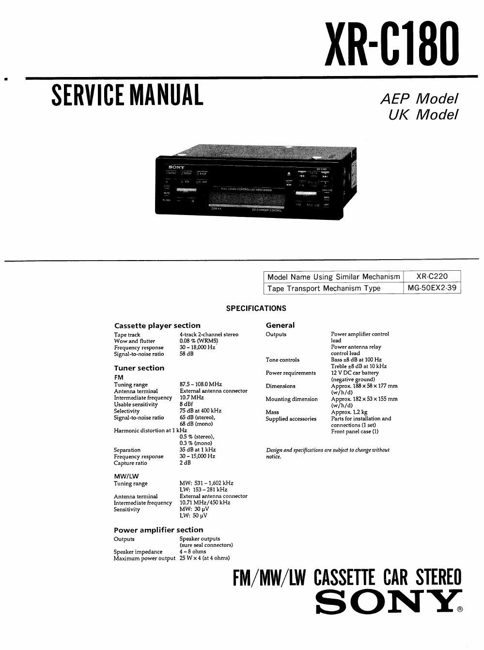
This is the 36 pages manual for sony xr c 180 service manual.
Read or download the pdf for free. If you want to contribute, please upload pdfs to audioservicemanuals.wetransfer.com.

Page: 1 / 36
sony xr c 180 service manual

Extracted text from sony xr c 180 service manual (Ocr-read)


Page 1

XR-CIBU

SERVICE MANUAL AEP Model

UK Model

Model Name Using Similar Mechanism XR-CZZO
Tape Transport Mechanism Type MG-50EX2-39

SPECIFICATIONS

Cassette player section General
Tape track Lirack Z-channel stereo Outpuls Power amplifier control
Wow and flutter 0,08 % (WRMS) lead
Frequency response 30 - 18,000 Hz Power antenna relay
Si gnal-to-noisc ratio 58 dB control lead
Tone controls Bass :8 dB at 100 Hz
Tuner section . Treble :BdBat 10 kHz
FM Power requirements :2 V DC car bang}!
n alive oun

Tuning 5 575 " 1080 MHz Dimensions Aggro; 1%; X 58 x 177 mm
Antenna terminal External antenna connector (w/h N}
lemma frf-"-'Ie"3) 10-7 MHz Mounting dimension Approx. 182 x 53 x 155 mm
Usable sensitivnty a «mi M, ,d)
Selectivity 75 dB at 400 kHz Mass Approx L2 kg
Signal-tonoise Ii" 65 d5 (stereo), Supplied accessories Parts for installation and

63 dB (mono) connections (I set)
Harmonic distortion at 1 kHz Front panel case (1)

0.5 70 (stereo),

0,3 % (mono)
Separation 35 dB at 1 kHz Dsign and specifications are Subject in thing: without
Frequency response 30 - 15,000 Hz notice,
Capture ratio ZdE
MW/ LW
Tuning range MW: 531 -1(602 kHz

LW: 153- 281 kHz
Antenna temiinal External antenna connector
Intermediate frequency 1031 MHz/450 kHz
Sensitivity MW: so pV

LW: so pV

Power amplifier section

Outputs Speaker outputs
(sure seal connectors)

FM/MW/LW CASSETTE CAR STEREO
S 0 NY;

Page 2

Notes on Chip Component Replacement

Never reuse a disconnected chip component.

- Notice that the minus side of a tantalum capacito may
be damaged by heat.

2-1.
22.
2-3.
2-4.

3-1.
3-2.
3-3.
3-4.
3-5.
36.
3-7.

6-1.
6-2.
6-3.
6-4.
65.

7»1i
7-2.
7-3.

TABLE OF CONTENTS

GENERAL
Location of controls ................................ 3
Getting Started .................................... 3

Cassette Player
Radio .........
Other Functions . . .

CD Changer ...............

Additional Information

Connections ...............

DISASSEMBLY
Sub Panel Assy ................................ 10
Heat Sink ...................................... 10
Mechanism Deck Block i . l .11
Main Board ,. ., . .Il

ASSEMBLY OF MECHANISM DECK
Installing the Loading Gears
Installing the Reel Bracket .. . . .
Installing the Mode Lever and Pinch Levers ...... 13

Installing the Cassette Housing ..

Installing the Loading Lever

Positioning the Loading Levers , , .

Installing the Gear (Loading F) .................. 15
MECHANICAL ADJUSTMENTS .................. 16

ELECTRICAL ADJUSTMENTS
Deck Section ..................
Tuner Section

..16

DIAGRAMS
IC Pin Description .............................. 20
Printed Wiring Boards-Main Sectioni .......... 22
Schematic Diagram~Main Section~ . .25
Printed Wiring BoardiPanel Section- .i . .30
Schematic Diagram-Panel Section- ............ 32
EXPLODED VIEWS
Chassis Section .................................. 37
Front Panel Section ............................ 38
Mechanism Deck Section ........................ 39
ELECTRICAL PARTS LIST ...................... 40