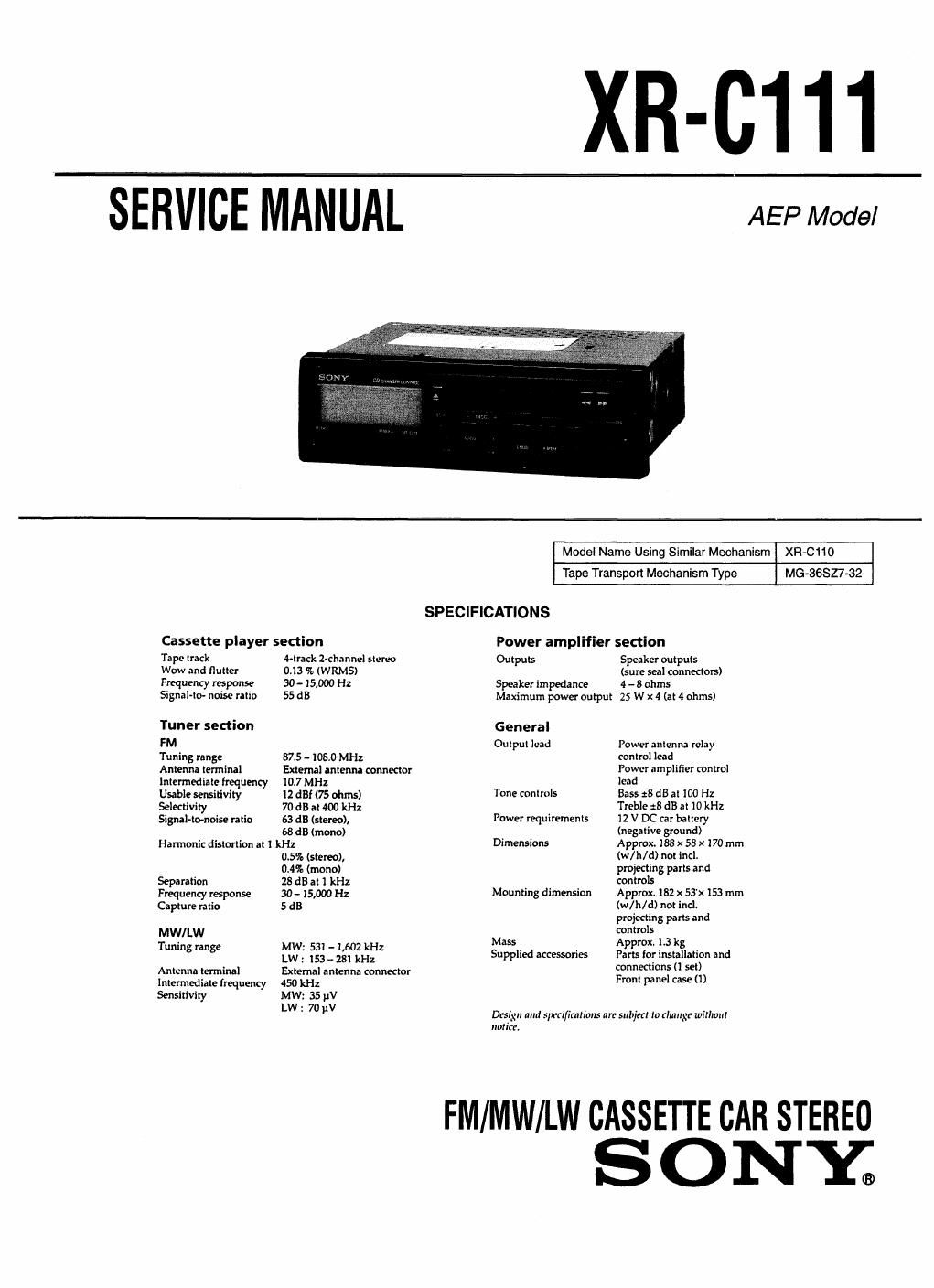
Sony xr c 111 service manual
This is the 31 pages manual for sony xr c 111 service manual.
Read or download the pdf for free. If you want to contribute, please upload pdfs to audioservicemanuals.wetransfer.com.
Extracted text from sony xr c 111 service manual (Ocr-read)
Page 1
XR-CIII
SERVICE MANUAL
AEP Model
Cassette player section
Tape lrack rack z-chnnncl stereo
Wow and flutter 0.13 % (WRMS)
Frequency response 30 - 15,000 Hz
Signal-Kr noise ratio 55 dB
Tuner section
FM
Tuning range 87.5 - 108.0 MHz
Antenna terminal External antenna connector
immediate frequency 107 MHz
Usable sensitivity 12 dBf (75 ohms)
Selectivity 70 dB at 400 kHz
Signal-tomoise ratio 63 dB (stereo),
68 dB (mono)
Harmonic distortion at 1 kHz
0.5% (stereo),
0.4% (mono)
Separation 28 dB at I kHz
Frequenq response 30- 15,000 Hz
Capture ratio 5 dB
MW/LW
Tuning range MW: 531 - 1,602 kHz
LW : 153 e 281 kHz
Antenna terminal External antenna connector
Intermediate frequency 450 kHz
Sensitivity MW: 35 pV
LW : 7o pV
Model Name Using Similar Mechanism XR-Cflo
Tape Transport Mechanism Type MG-SGSZ7-32
SPECIFICATIONS
Power amplifier section
Outputs Speaker outputs
(Sure seal connectors)
Speaker impedance 4 - 8 ohms
Maximum power output 25 W x 4 (at 4 ohms)
G eneral
Output lead Power antenna relay
control lead
Power amplifier control
lead
Tone controls Bass :8 dB at 100 Hz
Treble :8 dB at 10 kHz
Power requirements 12 V DC car battery
(negative ground)
Dimensions Approx. 188 x 58 x 170 mm
(w/h/d) not incl.
projecting parts and
controls
Mounting dimension Approx. 182 x 53'x153 mm
(w/h/d) not incl.
projecting parts and
controls
Mass Approx, 1.3 kg
SuPplied accessories Parts for installation and
connections (I set)
Front panel case (i)
Drsign and slurrfirntinns are subject to (hang: wirlwnl
"mice.
FM/MW/LW CASSETTE CAR STEREO
SONY.
Page 2
TABLE OF CONTENTS
1. GENERAL
Button Locations
Setting the Clock
Cassette Player Opera on
Radio Reception
Other Functions.
CD Changer Operation
Maintenance i.
Connections
2. DISASSEMBLV
2-1. Cover .........
2-2. Lock Assy ..
23. MD Block.
2-4. Heat Sink
2-5r Main Board ........... 1
3. MECHANICAL ADJUSTMENTS .............................. 11
4. ELECTRICAL ADJUSTMENTS
Deck Section .....
Tuner Section
. DIAGRAMS
5-1. IC Pin Description
5-2. Printed Wiring Boards
5-3. Schematic Diagram 4.
6. EXPLODED VIEWS
6- L Chassis Section ......
6-2. Front Panel Section
6-3. Mechanism Section (1)
6-4. Mechanism Section (2)
7. ELECTRICAL PARTS LIST ...................................... 31
Notes on Chip Component Replacement
- Never reuse a disconnected chip component.
oloQo'oo'oe
- Notice that the minus side of a tantalum capacitor may be dam-
aged by heat.