Sony xr a 55 service manual

This is the 30 pages manual for sony xr a 55 service manual.
Read or download the pdf for free. If you want to contribute, please upload pdfs to audioservicemanuals.wetransfer.com.

Page: 1 / 30
sony xr a 55 service manual

Extracted text from sony xr a 55 service manual (Ocr-read)


Page 1

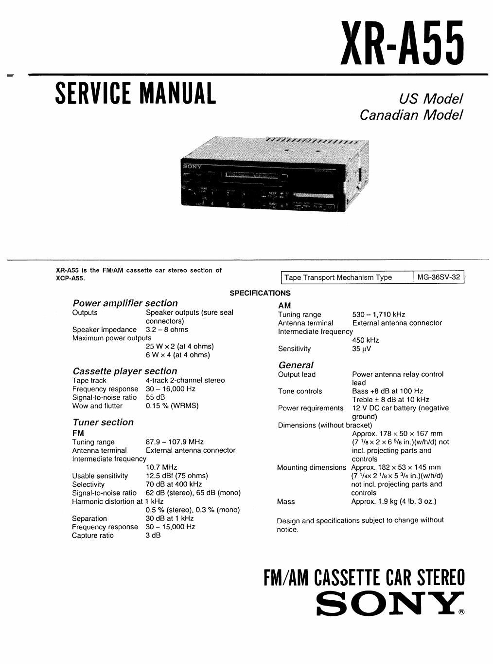
XR-A55

SERVICE MANUAL us Model

Canadian Model

XR-A55 is the FM/AM cassette car stereo section of

XCP-Ass. Tape Transport Mechanism Type MG-SSSV-azj
SPECIFiCATIONs
Power amplifier section AM
Outputs Speaker outputs (sure seal Tuning range 530 _ 1,7,0 kHz
' COMSCAOFS) Antenna terminal External antenna connector
Speaker impedance 3-2 - 8 ohms Intermediate lrequency
Maximum power outputs 450 kHz
25 W X 2 (at 4 Ohms) Sensitivity 35 (iv
6 w x 4 (at 4 ohms)
C I t' General
asselte P ayer sec 0" Output lead Power antenna relay control
Tape track 4-track 2-channel stereo lead
Frequency 9590, 30 ' 16900 HZ Tone controls Bass +8 dB at 100 Hz
Signaleto-notse ratio 55 dB Treble 1: 8 dB at 10 kHz
WOW and "e' 0-15 % (WRMS) Power requirements 12 V DC car battery (negative
. ground)
Tuner seeton Dimensions (without bracket)
FM Approx. 178 x so x 167 mm
Tuning range 87.9 - 107.9 MHz (7 /e x 2 x 6 5/5 in.)(w/h/d) not
Antenna terminal External antenna connector incl. projecting pans and
Intermediate lrequency controls
10.7 MHz Mounting dimensions Approx. 182 x 53 x 145 mm
Usable sensitivity 12.5 dBi (75 ohms) (7 lax 2 la x 5 3/4 in.)(wlh/d)
Selectivity 70 dB at 400 kHz not incl. projecting parts and
Signal-tomoise ratio 62 dB (stereo), 65 dB (mono) controls
Harmonic distortion at 1 kHz Mass Approx. 1.9 kg (4 lb. 3 oz.)
0.5 % (stereo). 0.3 % (mono)
Separation 30 dB at 1 kHz Design and specifications subiect to change without
Frequency response 30 - 15,000 Hz notice.
Capture ratio 3 dB

FM/AM CASSETTE CAR STEREI]

SONY;

Page 2

I

XR-A55

TABLE OF CONTENTS

LCM 1142 Page
Specifications .................................. 1
1. GENERAL
Installation .............................. 3
Connections ............................. 4
Location and Function of Controls ~~~~~~~~~~~ 6
Tape Playback ........................... 7
Automatic Tuning ........................ 7
Manual Tuning ........................... 3
Memory Preset Tuning .................... 8
Disc playing ............................. 9
2. ADJUSTMENTS
2-1. Mechanical Adjustment .................... 10
2-2 Electrical Adjustments ~~~~~~~~~~~~~~~~~~~~ 10
Deck Section ............................ 10
TUner Section ............................ 1]
3. DIAGRAMS
3-1. ICOOl ( fl PD75116GF-F01-3BB) ~~~~~~~~~~ 14
3.2. Block Diagram ........................... 17
3-3. Schematic Diagram ~~~~~~~ ~ ~ . . 19
3-4. Printed Wiring Boards ----- . 23
4. EXPLODED VIEWS .................... 27
5. ELECTRICAL PARTS LIST ------------ 32