Sony xr 7192 service manual

This is the 30 pages manual for sony xr 7192 service manual.
Read or download the pdf for free. If you want to contribute, please upload pdfs to audioservicemanuals.wetransfer.com.

Page: 1 / 30
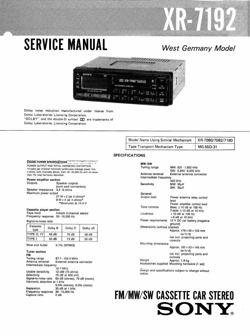
sony xr 7192 service manual

Extracted text from sony xr 7192 service manual (Ocr-read)


Page 1

SERVICE MANAL

Dolby noise reduction manufactured under license from

Dolby Laboratories Licensing Corporation.

"DOLBY" and the double-D symbol DD are trademarks of

Dolby Laboratories Licensing Corporation,

[Auoftiiowaaisem , , , _
POWER OUTPUT AND TOTAL HARMONIC DlSTORTION

14 watts per channel minimum continuous average power into

4 ohms. both channels driven. Irom 40-20000 HZ wllll no more
than 1% total harmonic distortion.

Power emplltler section
Outputs Speaker outputs
(sure seal connectors)
Speaker impedance 3,2-8 ohms
Maximum power output
27 W x 2 (at 4 ohms)
9 Wx4 (at 4 ohms)
'Measured at 14.4 V

Cassette player secllon
Tape track rack 2»channel stereo
Frequency response filo-15,000 Hz

Signal-to-noise retio

Cassette
type Dolby B Dolby C Dolby oil
TYPE II. IV 66 dB 76 dB 58 dB
TYPE I 63 dB 73 dB 55 dB

Wow and llutter 0.1% (WRMS)

Tuner section

Tuning range e7.5-1oe.o MHz
Antenna terminal External antenna connector
Intermediate lrequency

10.7 MHz
Usable sensitivity 12 dB! (75 ohms)
Selectivity 75 dB at 400 kHz

Signel-to-nolse ratio 65 dB (stereo), 70 dB (mono)
Harmonic distortion at 1 kHz
0.5% (stereo), 03% (mono)

Separation 35 dB at 1 kHz
Frequency response 30- 15.000 Hz
Capture ratio 2 dB

Model Name Using Similar Mechanism XR-7080/7082/7180

Tape Transport Mechanism Type MG-55D-31
SPECIFICATIONS
MW/SW
Tuning range MW: 531 -1,602 kHz
SW: 5,9506205 kHz
Antenna terminal External antenna connector
Intermediate lrequency
450 kHz
Sensitivity MW: 35W
SW: 35pV
General
Output lead Power antenna relay control
lead
Power amplifier control lead
Tone controls Bass :10 dB at 100 Hz
Treble 110 dB at 10 kHz
Loudness +10 dB at 100 Hz

+ 6 dB at 10 kHz
Power requirements 12 V DC car battery (negative
ground)
Dimensions (without bracket)
Approx. 178 x 50 x153 rnm
(w/h/d)
not incl. projecting parts and
controls
Mounting dimensions
Approx. 182 x 53 X145 mm
(w/h/d)
not incl. projecting parts and
controls
Weight Approx. 1.9 kg
Accessories supplied Mounting hardware (1 set)

Design and specifications subject to change without
notice.

FM/MW/SW CASSETTE CAR STEREI]
S ONY;

Page 2

XR-71 92

eatu res

Tuner section

0 SSlR (Sony Super Interference Rejection)
PLL Synthesizer tuner

- Automatic memory function stores a total of
24 stations in memory quickly and easily.

0 Memory scan function scans preset stations
each for five seconds in order.

Cassette deck section

- The auto-reverse function changes tape
directions automatically.

-The C-type Dolby NR system is incorpo-
rated as well as the B-type Dolby NR
system.

. Intro play scans the beginning of each
selection sequentially.

. The repeat play function enables a repeat
play of the selection you are now listening
to.

OThe blank skip function automatically skips
the blank portion longer than eight seconds
and plays back the next selection.

0 The ATA (Automatic Tuner Activation)
function automatically turns on the tuner
while last-winding a tape.

Section Title

Specifications .............................

Features

1. GENERAL

Location and Function of Controls ------

installation
Connections
Tape Playback
Automatic Tuning -------
Manual Tuning ----------
Memory Preset Tuning
Maintenance

2. DISASSEMBLY --------------------

3. ADJUSTMENTS

3-1. Mechsanical Adjustments
3-2. Electrical Adjustments
Deck Section
Tuner Section

..... 3

CD section (when the optional Sony CD
changer is connected)

OThe intro play function plays the first ten
seconds of each selection on every disc,
.The repeat play function enables a repeat

play of the selection you are now listening
to,
- The disc scan function plays the first ten
seconds of the first selection on each disc.
~The shuffle play function plays selections in
random order.

I The ATA function automatically turns on the
tuner while changing discs.

- Manual search allows you to search for a
desired point in a selection.

TAB LE OF CONTENTS

Page

..... 1

..... 11

~13
'13
~13
~15

Section Title Page
4. DIAGRAMS
. 4-1. Tuner Unit Schematic Diagram ------------- 19

4-2. IC501( [z PD755166) Functional

Description ................
4-3. Printed Wiring Boards ---------
4-4. Main Section Schematic Diagram
5. EXPLODED VIEWS -------------------- 31
6. ELECTRICAL PARTS LIST ------------ 36
Mounting Hardware ----------------------------- 42