Sony xr 7080 service manual

This is the 36 pages manual for sony xr 7080 service manual.
Read or download the pdf for free. If you want to contribute, please upload pdfs to audioservicemanuals.wetransfer.com.

Page: 1 / 36
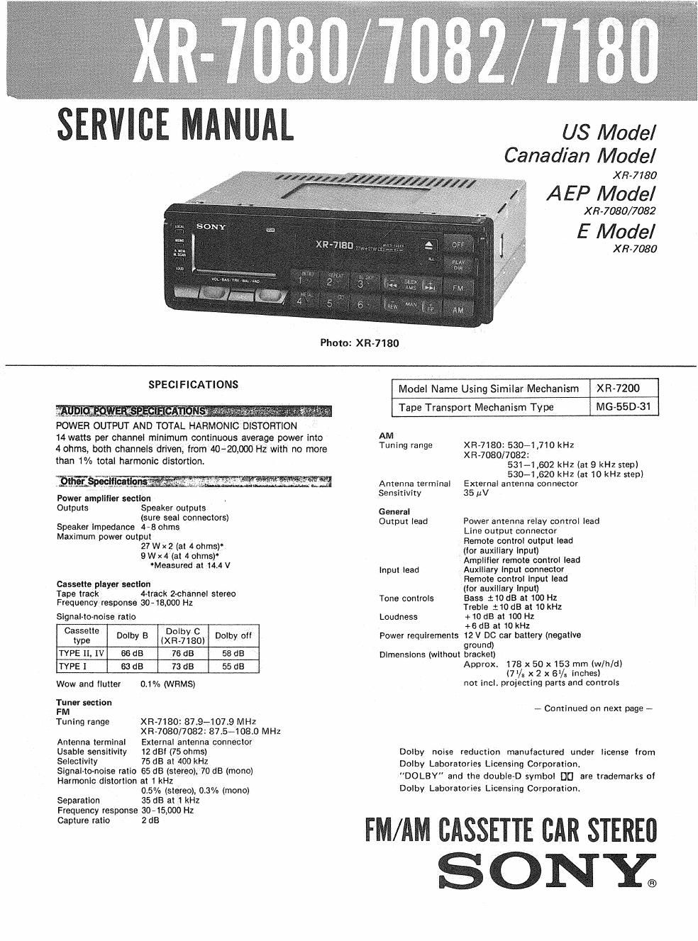
sony xr 7080 service manual

Extracted text from sony xr 7080 service manual (Ocr-read)


Page 1

US Model
Canadian Model

X 8-7 780

A EP Model

X 3-7080/7082

E Model

X R7080

Photo: XR-7180

SPECIFICATIONS

_ 'li'iétiflilif -

POWER OUTPUT AND TOTAL HARMONIC DISTORTION
14 watts per channel minimum continuous average power into
4 ohms, both channels driven, from 4040,0013 Hz with no more
than 1% total harmonic distortion.

Power amplliier section
Outputs Speaker outputs

(sure seal connectors)
Speaker impedance 4-8 ohms
Maximum power output
27 W x2 (at 4 ohms)
9 W x 4 (at 4 ohms)
Measured at 14.4 V

Cassette player section
Tape track 4-track 2-channel stereo
Frequency response 30-18,000 Hz

Signal-to-noise ratio

Cassette Dolby C
type mm B lXR-7180) my °
TYPE 11, iv 66 dB 76 aa 58 us
TYPE I so dB 73 as 55 as

Wow and ilutter 0.1% (WRMS)
Tuner section

XR-7180187.9-107.9 MHz
XR-7080/7082: 87t5A108.0 MHz
Antenna terminal External antenna connector
Usable sensitivity 12 dBi (75 ohms)

Selectivity 75 dB at 400 kHz

Signal-tonoise ratio 65 dB (stereo), 70 dB (mono)
Harmonic distortion at 1 kHz

05% (stereo), 0.3% (mono)

Tuning range

Separation 35 dB at 1 kHz
Frequency response $045,000 Hz
Capture ratio 2 dB

Model Name Using Similar Mechanism XR-7200
MG-55D-31

Tape Transport Mechanism Type

AM
Tuning range XR-7180: 53071.710 kHz
XR-7080/7082:
531-1 .602 kHz (at 9 kHz step)
530~1,620 kHz (at 10 kHz step)
Antenna terminal External antenna connector

Sensitivity 35 MV
General
Output lead Power antenna relay control lead

Line output connector
Remote control output lead
(for auxiliary lnput)
Amplliler remote conirol lead
input lead Auxiliary lnput connector
Remote control input lead
(for auxiliary lnput)
Bass :10 dB at 100 Hz
Treble i 10 dB at 10 kHz
Loudness + 10 dB at 100 Hz
+6 dB at 10 kHz
Power requirements 12 V DC car battery (negative
ground)
Dimensions (without bracket)
Approx. 178 x 50 x153 mm (w/h/dl
(71/23 x 2 x Bl/t inches)
not incl. projecting parts and controls

Tone controls

- Continued on next page -

Dolby noise reduction manufactured under license from
Dolby Laboratories Licensing Corporation.
"DOLBY" and the doubieD symbol DI] are trademarks of
Dolby Laboratories Licensing Corporation.

FM/AM CASSETTE CAR STEREU

SONE

Page 2

XR-7080/7082/7180

Mounting demensions

Weight

Approx 182 x 53 x 145 mm tw/h/dl
(7% x 21/3 x 53/. inches)
not incl. projecting parts and controls

Approx. 1.9 kg (4 lb 3 oz)

Accessory supplied Mounting hardware (1 set)

TABLE OF CONTENTS

Section Title Page
Specifications ....................... 1
Note on Repairing .................... 2
1. GENERAL
Location and Function of Controls ..... 3
Installation ..................... 5
Connections .................... 6
Tape Playback ................... 8
Automatic Tuning ................ 8
Manual Tuning ................... 9
Memory Preset Tuning .............. 9
Maintenance .................... 9
2. DISASSEMBLY .................. 10

[NOTE ON REPAIRING]

Note on Repairing AMP Board

When repairing AMP Board removed from the
chassis as shown in Fig. 1, check or repair it con-
nected with lead wires and such like.

When Checking AMP Board separately, connect
with a lead wire between ground patterns as shown
in Fig 2.

. After repairing, remove the lead wire.

Section Title Page
3. ADJUSTMENTS
3-1. Mechanical Adjustment ............. 12
3-2 Electrical Adjustments .............. 12
4. DIAGRAMS
4~1. IC301 (pPD75108G-E61) Description . . l 17
IC Block Diagrams ................ 22
4-2. Tuner Section Schematic Diagram ...... 23
4-3. Printed Wiring Boards .............. 26
4-4. Main Section Schematic Diagram ....... 31
5. EXPLODED VIEWS ............... 37
6. ELECTRICAL PARTS LIST ......... 42

AMP board

Ground lead wire

Fig. 7

lead wire (between ground patterns)

Fig. 2

__2_