Sony xr 7070 service manual

This is the 38 pages manual for sony xr 7070 service manual.
Read or download the pdf for free. If you want to contribute, please upload pdfs to audioservicemanuals.wetransfer.com.

Page: 1 / 38
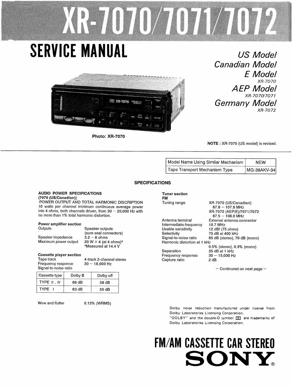
sony xr 7070 service manual

Extracted text from sony xr 7070 service manual (Ocr-read)


Page 2

XR-7070/7071/7072

AM (MW/LW)

Tuning range

Antenna terminal

XR-7070 (US/Canadian):
530 - 1710 kHz
XR-7070 (AEF'IE)I7072
European and other countries
531 - 1,602 kHZ
(at 9 kHz step)
North and South American
countries
530 - 1,620 kHz
(at 10 kHz step)
AM tuning interval 9 kHz/
10 kHz switchable
XR-7071:
MW 531 - 1,602 kHZ
LW 153 - 281 kHZ
exterminal antenna connector

General

0 utput lead

Tone controls

Power antenna relay control lead
Power amplifier control lead
Bass i 10 dB at 100 Hz

Treble i 10 dB at 10 kHz
Loudness +6 dB at 100 Hz
+6 dB at 10 kHz
Power requirements 12 V DC car battery
(negative ground)

Dimensions (without bracket)

Mounting dimensions

Weight
Accessories supplied

Approx. 178 X 50 X 167 mm
(w/h/d)

(7lu X 2 X 6]. inches)

not incl. projecting parts and
controls

Approx. 182 X 53 X 145 mm
(w/h/d)

(7/. X 2]. X 5l4 inches)

not incl. projecting parts and
controls

Approx. 2 kg (4 lb. 7 oz.)
Mounting hardware (1 set)

Design and specifications subject to change without notice.

TABLE OF CONTENTS

Intermediate frequency 450 kHz
Sensitivity XRA7070/7072:
35 11 V
XR-7071:
MW 35 11V
LW 70 11V
Section Title Page
Specificafions .................................. 1
1. GENERAL
Installation/installationMontage ------------ 3
Connections/Connexions/Aansluitingen ------ 5
Location and Function of Controls ~~~~~~~~~~~ 7
Tape Playback ........................... 9
Automatic Tuning ---------------
Manual Tuning -----
Memory Preset Tuning - 11
Disc Playing ------- 12
Maintenance ..................... 12
2. DISASSEMBLY ......................... 13
3. ADJUSTMENTS
3-]. Mechanical Adjustments --------
3»Z, Electrical Adjustments
Deck Section - 15
Tuner Section ............................ 17
DIAGRAMS
4-1. [€301 u PD75116GF-625-3BE
(Micro Computer) ........................ 20


Section [11% P_ag§
4-2. [C Block Diagrams ----------------------- 23
4-3. Printed Wiring Boards

(Type A: XR-7070 (US) Main board

part numbec 1-634-042-11) ---------------- 25
4-41 Schematic Diagrams

(Type A: XR-7070 (US) Main board

part number. l-634>042-11) ---------------- 29
4-5. Printed Wiring Boards

(Type B: XII-7070 (Canadian/AEP/E)/7071

/7072 and XR-7070 (US) Main board

part number. 1-634-042-13) ---------------- 35
4-6. Schematic Diagram

(Type B: XII-7000 (Canadian/AEP/E)/7071

/7072 and XR-7070 (US) Main board

part number. 1-634-042- 13) ---------------- 39
5_ EXPLODED VIEWS .................... 44
6. ELECTRICAL PARTS LIST ~~~~~~~~~~~~ 50
Mounting Hardware ............................. 56