Sony xr 5508 service manual

This is the 24 pages manual for sony xr 5508 service manual.
Read or download the pdf for free. If you want to contribute, please upload pdfs to audioservicemanuals.wetransfer.com.

Page: 1 / 24
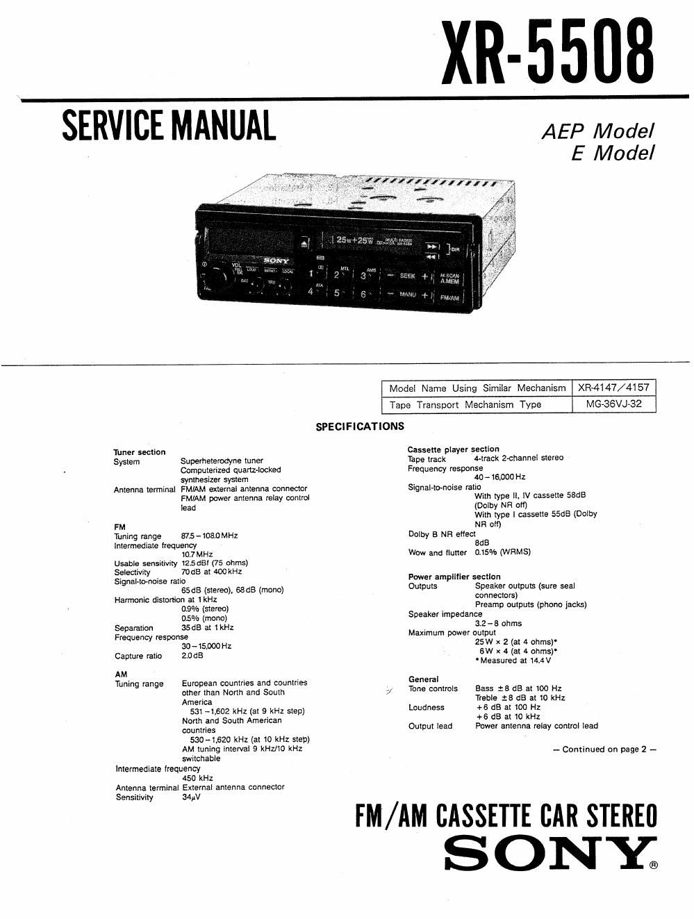
sony xr 5508 service manual

Extracted text from sony xr 5508 service manual (Ocr-read)


Page 1

X_R-_55_08_

SERVICE MANUAL

AEP Model
E Model

XR41147/41 57
MG-SSVJ-ESZ

Model Name Using Similar Mechanism

Tape Transport Mechanism Type

SPECIFICATIONS

Tuner section

System Superheterodyne tuner

Computerized quartz-locked

synthesizer system

Antenna terminal FMIAM external antenna connector
FMIAM power antenna relay oontrol

lead
FM
Tuning range 875-1080 MHz
intermediate frequency

10.7 MHz

Usable sensitivity 12.5 dB! (75 ohms)
Selectivity 70:18 at 400kHz
SignaHo-noise ratio

65d8 (stereo), GSdB (mono)
Harmonic distortion at 1 kH:

09% (stereo)
05% (mono)
Separation 35GB at (Hz
Frequency response
30-15000 Hz
Capture ratio 2.0 (18
AM
Tuning range European countries and countries
other than North and South 7'
America

531 -1,602 kHz (at 9 kHz step)
North and South American
countries
530-1.620 kHz (at 10 kHz step)
AM tuning interval 9 KHZJIO kHz
switchable
Intermediate lrequency
450 kHz
Antenna terminal External antenna connector
Sensitivity 34W

Cassette player section
Tape track 4-track Z-channel stereo
Frequency response
40 - 16.000 Hz
Signal-tonoise ratio
With type II, IV cassette 58GB
(Dolby NH 0)
With type I cassette 55d8 (Dolby
NR oil)
Dolby 3 NR etlect
BdB
Wow and flutter (5% (WRMS)

Power amplifier section
Outputs Speaker outputs (sure seal
connectors)
Preamp outputs (phone jacks)
Speaker impedance
3.2 - 5 ohms
Maximum power output
25W x 2(314 ohms)
6W x 4 (at 4 onms)
' Measured at 144V

General
Tone controls Bass :8 dB at 100 Hz

Treble :8 dB at 10 kHz

Loudness +6 dB at 100 Hz
+6 dB at 10 kHz
Output lead Power antenna relay control lead

- Continued on page 2 -

FM/AM CASSETTE CAR STEREfl

SONY;

Page 2

XR-5508 1

Power requirements

12 V DC car battery (negative TABLE OF CONTENTS
ground)
Dimensions Approx. 178 x 50 x 160 mm (wlhld)
(7!g x 2 x s3!8 inches) Section Title Page
not incl. projecting parts and
controls . . .
Mounting dimensions Specrfications ..................................................................... 1

Approx. 182 x 53 x145 mm w/h/d)
(71 x 2I5 x 53/4 inches)

not incl. projecting parts and 1. GENERAL
W h 2mm]: 1:! kg (2 lb ) 1-1. Location and Function of Controls ----------------------- 3
eig t pprox. 4 oz .
Accessories supplied 1-2. Installation ~ 4
Mounling hardware (1 set) 1-3, Connections 5
Design and specifications subject to change wimoul
notice. 2. ADJUSTMENTS .......................................................... 5

3. DlAGRAMS
3«1. Semiconductors Lead Layout-
3-2. Printed Wiring Board
33. Schematic Diagram-

4. EXPLODED VIEWS -

5, ELECTRICAL PATRS LIST~

Flexible Circuit Board Repairing MODEL IDENTIFICATION
0 Keep the temperature of the soldering iron around

270°C during repairing. SONY MODEL NO. XR-5508

I Do not touch the Soldering iron on the same conduc-
torofthecircuit board (within3times). ' FM/AM CASSETTE CAR STEREO
0 Be careful not to apply force on the conductor when F R EQ U E N CY RAN G E ;
soldering or unsoldering. FM 87.5~108.0MH2

AM 531~1602kHz (9k STEP)

Notes on chip component replacement 530~1620kHz (10k STEP)
0 Never reuse a disconnected chip component. DC ; 12v: NEGATIVE GROUND
0 Notice that the minus side of a tantalum capacitor

may be damaged by heat. SERIAL NO'

MADE IN. MALAYSIA