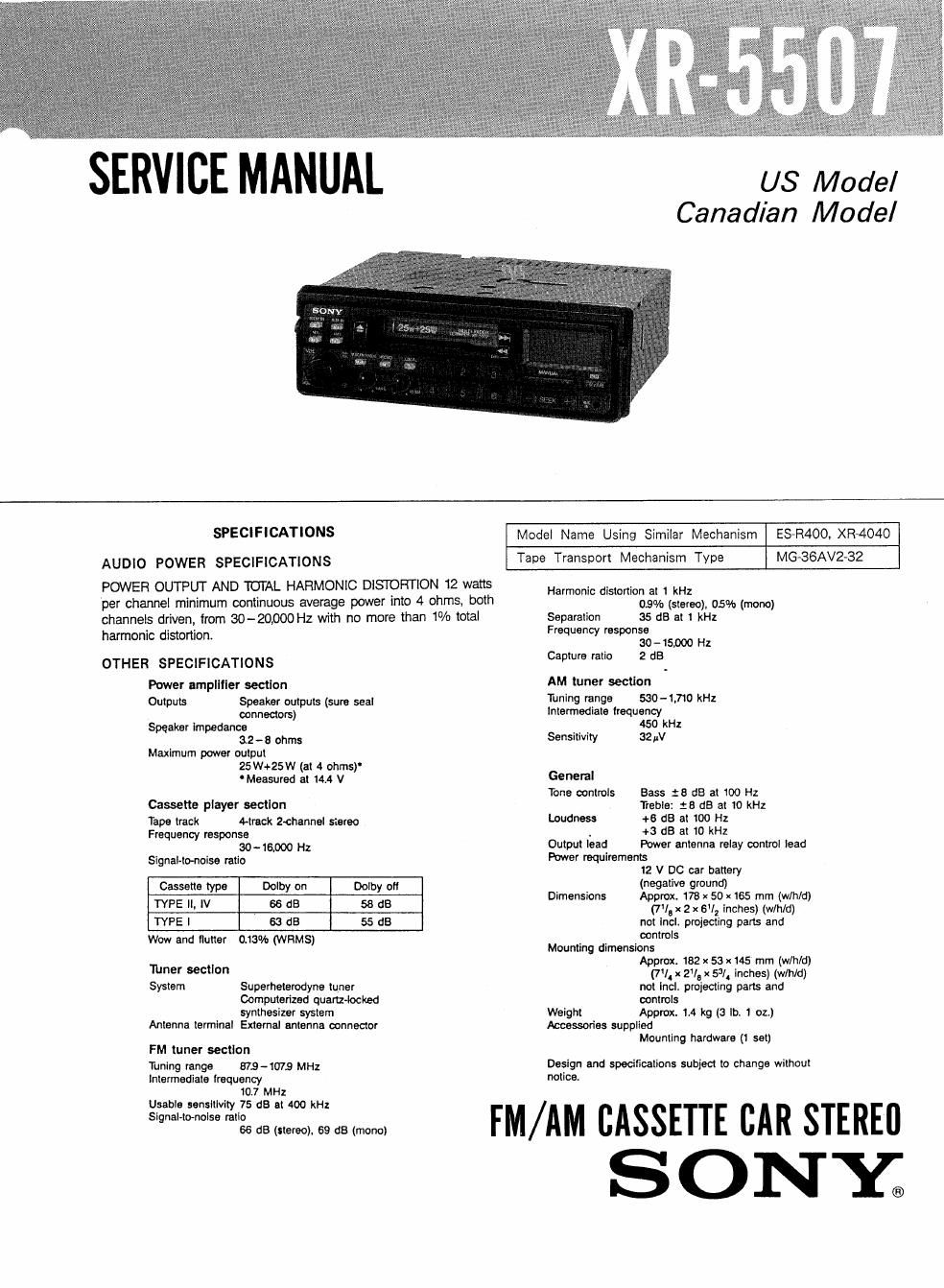
Sony xr 5507 service manual
This is the 25 pages manual for sony xr 5507 service manual.
Read or download the pdf for free. If you want to contribute, please upload pdfs to audioservicemanuals.wetransfer.com.
Extracted text from sony xr 5507 service manual (Ocr-read)
Page 1
SERVICE MANUAL
US Model
Canadian Model
SPECIFICATIONS
AUDIO POWER SPECIFICATIONS
POWER OUTPUT AND TOTAL HARMONIC DlSTOFlTlON 12 watts
per channel minimum continuous awerage power into 4 ohms, both
channels driven, from GEO-20,000 Hz with no more than 1% total
harmonic distortion.
OTHER SPECIFICATIONS
Power ampllller section
Outputs Speaker outputs (sure seal
connectors)
Speaker impedance
32 - 8 ohms
Maximum power output
25 W+25W (at 4 ohms)
Measured at 14.4 V
Cassette player section
Tape track A-treck Z-ohannel stereo
Frequency response
(BO-16,000 Hz
Signal-to-neise ratio
Cassette type Dolby on Dolby 0"
TYPE II, IV 66 dB 58 dB
TYPE I 63 dB 55 dB
Wow and flutter 0.13% (WFIMS)
Timer section
System Superheterodyne tuner
Computerized quartz-locked
synthesizer system
Antenna terminal External antenna connector
FM tuner section
Tuning range 879-1072 MHz
Intermediate Iroquency
107 MHz
Model Name Using Similar Mechanism ESaR400. XR-404O
Tape Transport Mechanism Type MGa36AV2-32
Harmonic distortion at 1 kHz
0.9% (stereo). 05% (mono)
Separation 35 dB at 1 kHz
Frequency response
30 -15,000 Hz
Capture ratio 2 dB
AM tuner section
Tuning range sac-1,710 kHz
Intermediate trequency
450 kHz
Sensitivity 32!
General
Tone controls Bass :5 dB at 100 Hz
Treble: :8 dB at 10 kHz
Loudness +6 :15 at 100 Hz
1 +3 63 at 10 kHz
Output lead Power antenna relay oontrol lead
Power requirements
12 V DC car battery
(negative ground)
Dimensions Approx. 176 x 50 x 165 mm (w/h/d)
(7!. x 2 x 6V, inches) (th/d)
not Incl, projecting parts and
controls
Mounting dimensions
Approx. 152 x 53 x145 mm (w/h/d)
(71 x 2v, x 53/. inches) (wlhld)
not Incii projecting pans and
controls
Weight Approx. M kg (3 lb. 1 oz)
Accessories supplied
Mounting hardware (1 set)
Design and specifications subject to change without
notice.
:g:';':.;::i;?£tu§::2;::::dam, FM/AM CASSETTE CAR STEREll
SONXC
Page 2
XR-5507
FEATURES
Tuner section
0 SSIR (Sony Super Interference Rejection)
PLL synthesizer tuner allows precise tuning.
O Memory preset tuning allows you to store 6
stations for each band in memory.
Section
Specifications
TABLE OF CONTENTS
Title
Cassette deck section Features ..
0 The auto-reverse function changes the tape
direction automatically. 1- GENERAL . ~
. The Dolby B NR' We!" reduces tape hiss 1»1. Location and Function of Controls
noise during playback. 1.2. installation ........................................
, The METAL button '0, htgh-perforrnance 1.3. Connections ....................................................... 5
metal tapes.
- Automatic Music Sensor (AMS) for locating 2. ADJUSTMENTS-~
the beginning or a selection during tape
playback. 3. DIAGRAMS
Power amplifier section
Provided with the muitl-fader system for
controlling the balance ol the front and rear
speakers in a 4-speaker system with an
additional amplifier and the built-in amplifier.
General 4
- The AUX IN jack on the lrorrt panel for easily
connecting auxiliary source equipment, such 5.
as Discman.
0 Provided with the auto-loudness circuit for
automatically reinforcing has and treble when
listening at low volume.
- Slide-out security bracket allows you to lake
the unit away with you when you leave your
car.
'Doloy noise reduction manufactured under license
from Dolby Laboratories Licensing Corporation.
COLBY and the doubleD symbol DU are
trademarks oi Dolby Laboratories Licensing
Corporation.
Flexible Circuit Board Repairing
0 Keep the temperature of the soldering iron around
270°C during repairing.
0 Do not touch the soldering iron on the same conduc-
tor of the circuit board (within 3 times).
0 Be careful not to apply force on the conductor when
soldering or unsoldering.
Notes on chip component replacement
0 Never reuse a disconnected chip component.
0 Notice that the minus side of a tantalum capacitor
may be damaged by heat.
34. Semiconductors Lead Layout ~12
3-2. Printed Wiring Boards ------- -13
3-3 Schematic Diagram-3 -17
34. FEi FM Front End Schematic Diagram~ -20
35 IC Block Diagrams-~ -21
EXPLODED VIEWS ........................................ . ............ 23
ELECTRICAL PARTS LIST ....................................... ..29