Sony xr 502 service manual

This is the 36 pages manual for sony xr 502 service manual.
Read or download the pdf for free. If you want to contribute, please upload pdfs to audioservicemanuals.wetransfer.com.

Page: 1 / 36
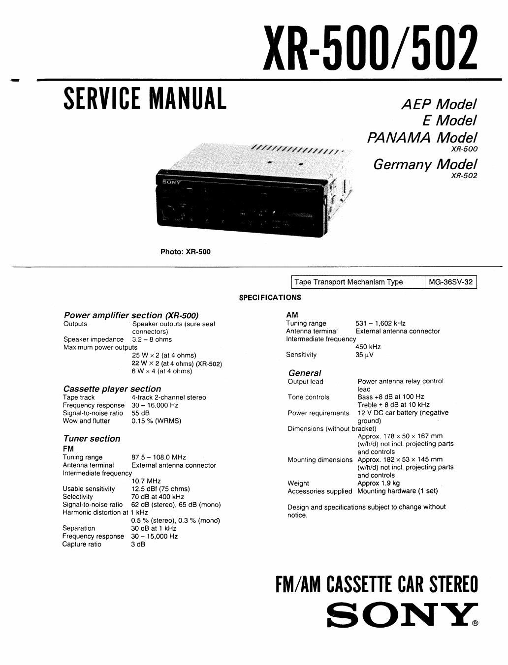
sony xr 502 service manual

Extracted text from sony xr 502 service manual (Ocr-read)


Page 1

XR-5UU/ 502

SERVICE MANUAL

Photo: XR-500

AEP Model
E Model
PANAMA Model

4 1 //f[((x1// // / l / , XR-500

Germany Model

X R~5 02

Power amplifier section (XE-500)
Outputs Speaker outputs (sure seal
connectors)
Speaker Impedance 3.2 - 8 ohms
Maxrrnum power outputs
25 W x 2 (at 4 ohms)
22 W X 2 (at 4 ohms) (XR-502)
6 W x 4 (at 4 ohms)

Cassette player section

Tape track 4»track 2-channel stereo
Frequency response 30 - 16,000 Hz
Signal-to-noise ratio 55 dB

Wow and flutter 0.15 /a (WFlMS)
Tuner section
FM
Tuning range 87.5 - 108.0 MHz
Antenna terminal External antenna connector
Intermediate frequency
107 MHZ
Usable sensitivity 12.5 (181 (75 ohms)
Selectivity 70 dB at 400 kHz

Signal-to-noise ratio 62 d8 (stereo). 65 dB (mono)
Harmonic distortion at 1 kHz
0.5 % (stereo). 013 % (mono)

Separation 30 dB at 1 kHz
Frequency response 30 - 15,000 Hz
Capture ratio 3 dB

Tape Transport Mechanism Type I MG-SSSV-Sil

SPECIFICATIONS

AM
Tuning range 531 - 1,602 kHz
Antenna terminal External antenna connector
Intermediate frequency
450 kHz
Sensitivity 35 (av
General
Output lead Power antenna relay control
lead
Tone controls Bass +8 :18 at 100 Hz

Treble 1 8 dB at 10 kHz

Power requirements 12 V DC car battery (negative
ground)

Dimensions (without bracket)
Approx. 178 x 50 x 167 mm
(w/h/d) not incl, projecting parts
and controls

Mounting dimensions Approx. 162 x 53 x 145 mm
(w/h/d) not incl, projecting parts
and controls

Weight Approx 1.9 kg

Accessories supplied Mounting hardware (1 set)

Design and specilications subject to change without
notice

FM/AM CASSETTE BAR STERED

SONY.

Page 2

XR-500/502

TABLE OF CONTENTS

Section Title Page

Specifications .................................. 1

1 . GENERAL

Installation

Connections
Location and Function of Controls - -
Tape Playback .....................
Automatic Tuning ..................
Manual Tuning .....................
Memory Preset Tuning ..............
Disc playing ...........
Maintenance .....................

\oxooowxlxxoxzsw

2. ADJUSTMENTS

2-1. Mechanical Adjustment -------------------- 10
2-2. Electrical Adjustments 10
Deck Section
Tuner Section ............................ 1 l

3. DIAGRAMS

3-1. 10001 (nPD75116GF-FOL3BE) - - 14
3-2. Block Diagram ............... 17
3-3. Schematic Diagram (XR»502)

3-4. Schematic Diagram (XR-SOO)

3-5. Printed Wiring Boards -------------

4. EXPLODED VIEWS -------------------- 33
5. ELECTRICAL PARTS LIST ------------ 38

Note for LItthm Battery

CAUTION
Danger of explosion if battery is incorrectly replaced.
Replace only with the same or equivalent type recom-
mended by the equipment manufacturer: Discard used
batteries according to manufacturers instructions

ADVARSEL I
Lithiumbatteri-Eksplosionsfare ved fejlagtig handtering.
Udskiftning m5 kun ske med batteri
af samme fabrikat og type.

Lever det brugte batted tilbage til Ievemndoren.

ADVARSEL
Lithiumbatteri-Eksplosjonsfare.
Ved utskifting bcnyttes kun batteri som
anbefalt av apparatfabrikanten.
Brukt batteri retumeres apparatleverandoren.

VARNING
Explosionsfara vid felaktigt batteribyte. Anvfind samma
batterityp eIler en likvardig typ som rekommenderas av
apparattillverkaren. Kassera anvant batteri enligt gallande
foreskn'fterr

VAROITUS
Paristo vci rfijitifi, jos se on virheellisesti asennettu Vaihda
paristo ainoastaan laitevalmistajan suosittelemaan tyyppiin.
Hévitii kaytetty paristo Valmistajan ohjeiden mukaisesti.