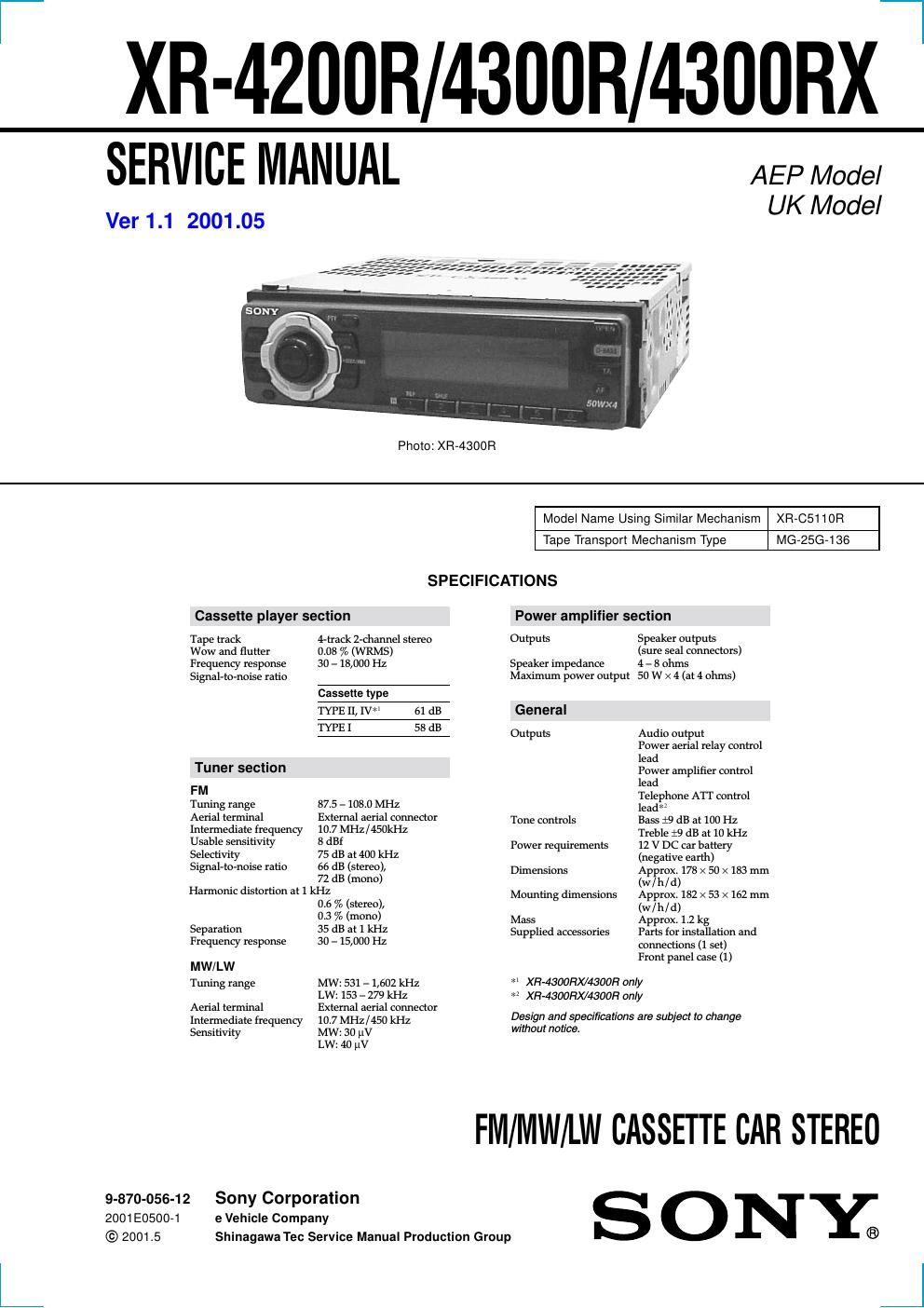
Sony xr 4300 r service manual

This is the 42 pages manual for sony xr 4300 r service manual.
Read or download the pdf for free. If you want to contribute, please mail your pdfs to info@audioservicemanuals.com.

Page: 1 / 42
left right
sony xr 4300 r service manual

Extracted text from sony xr 4300 r service manual (Ocr-read)


Page 1

2 Flexible Circuit Board Repairing - Keep the temperature of the soldering iron around 270 ˚C dur- ing repairing. - Do not touch the soldering iron on the same conductor of the circuit board (within 3 times). - Be careful not to apply force on the conductor when soldering or unsoldering. Notes on chip component replacement - Never reuse a disconnected chip component. - Notice that the minus side of a tantalum capacitor may be dam- aged by heat. TABLE OF CONTENTS 1. GENERAL Location of controls ........................................................ 3 Resetting the unit ............................................................ 3 Detaching the front panel ................................................ 3 Setting the clock .............................................................. 3 Installation ....................................................................... 4 Connections ..................................................................... 5 2. DISASSEMBLY ......................................................... 8 3. ASSEMBLY OF MECHANISM DECK ........... 10 4. MECHANICAL ADJUSTMENTS ....................... 13 5. ELECTRICAL ADJUSTMENTS ......................... 13 6. DIAGRAMS 6-1. Note for Printed Wiring Boards and Schematic Diagrams ....................................................... 15 6-2. Printed Wiring Board -“ MAIN Board (Component Side) -“ .............................. 16 6-3. Printed Wiring Board -“ MAIN Board (Conductor Side) -“ ................................ 17 6-4. Schematic Diagram -“ MAIN Board (1/2) -“ ................... 18 6-5. Schematic Diagram -“ MAIN Board (2/2) -“ ................... 19 6-6. Printed Wiring Board -“ KEY Board -“ ........................... 20 6-7. Schematic Diagram -“ KEY Board -“ ............................. 21 6-8. Printed Wiring Board -“ SUB Board -“ ........................... 22 6-9. Schematic Diagram -“ SUB Board -“ .............................. 22 6-10. IC Pin Function Description ........................................... 26 7. EXPLODED VIEWS ................................................ 30 8. ELECTRICAL PARTS LIST ............................... 33

Page 2

3 SECTION 1 GENERAL This section is extracted from instruction manual. 5 Location of controls Refer to the pages listed for details. 1MENU button 9, 11, 12, 13, 15, 17, 19, 22, 24 2Volume control dial 3SOURCE (TUNER/TAPE) button 8, 10, 12, 13, 16, 23 4 PRST +/-“ (cursor up/down) buttons 8, 9, 11, 12, 13, 15, 17, 18, 19, 22, 24 During radio reception: Preset stations select 13 5DSPL/PTY (display mode change/ programme type) button 11, 14, 18, 23, 24 6MODE button 10, 11, 12, 13, 23 During tape playback: Playback direction change 10 During radio reception: BAND select 12 7Display window 8 Z (eject) button (located on the front side of the unit behind the front panel) 10 9OPEN button 7, 10, 26 q;D-BASS button 23 qaSOUND button 21 qsOFF button* 2 7, 8, 10qdReset button (located on the front side of the unit behind the front panel) 7 qfSEEK/AMS -“/+ (cursor left/right) buttons 8, 9, 10, 11, 12, 13, 15, 17, 19, 21, 22, 24, 25Seek 13, 15 Automatic Music Sensor 10, 25 Manual search 13, 25 qgENTER button 9, 11, 12, 13, 15, 17, 18, 19, 22, 24 qhReceptor for the card remote commander* 3 qjNumber buttons During radio reception: Preset number select 12, 13, 16, 17 During tape playback: (1)REP 11 qkAF button 15, 17 qlTA button 16, 17 * 2Warning when installing in a car without ACC (accessory) position on the ignition key switch Be sure to press (OFF) on the unit for two seconds to turn off the clock display after turning off the engine. When you press (OFF) only momentarily, the clock display does not turn off and this causes battery wear. * 3XR-4300RX/4300R only DISC+PRST+- DISC-“ PRST-- SOURCE MODEDSPL AF OFF PTY ENTER MENU SOUND 1 2 3 4 56 -SEEK/AMS REP SHUF TA OPEND-BASS 7 A Attaching the front panelPlace the hole A of the front panel onto the spindle B on the unit as illustrated, then push the left side in. Notes - Be careful not to attach the front panel upside down. -Do not press the front panel too hard against the unit when attaching it. -Do not press too hard or put excessive pressure on the display window of the front panel. -Do not expose the front panel to direct sunlight or heat sources such as hot air ducts, and do not leave it in a humid place. Never leave it on the dashboard of a car parked in direct sunlight or where there may be a considerable rise in temperature. Caution alarmIf you turn the car ignition off without removing the front panel, the caution alarm will beep for a few seconds. If you connect an optional power amplifier and do not use the built-in amplifier, the beep sound will be deactivated. Getting Started Resetting the unit Before operating the unit for the first time or after replacing the car battery, you must reset the unit. Remove the front panel and press the reset button with a pointed object, such as a ballpoint pen. Note Pressing the reset button will erase the clock setting and some memorised functions. Detaching the front panel You can detach the front panel of this unit to protect the unit from being stolen. 1Press (OFF). 2Press (OPEN), then slide the front panel to the right side, and pull out from the left side. Notes - Be sure not to drop the panel when detaching it from the unit. -If you detach the panel while the unit is still turned on, the power will turn off automatically to prevent the speakers from being damaged. -When you carry the front panel with you, use the supplied front panel case.Reset button 1 2 x B 9 2 Press (ENTER). The clock starts. After the clock setting is complete, the display returns to normal playback mode. Tips -You can use the convenient CT function to set the clock automatically (page 19). -When the D.INFO mode is set to ON, the time is always displayed (page 22). Setting the clock The clock uses a 24-hour digital indication. Example: To set the clock to 10:08 1Press (MENU), then press either side of (PRST/DISC) or (PRST) repeatedly until CLOCK appears. 1 Press (ENTER). The hour indication flashes. 2 Press either side of (PRST/DISC) or (PRST) to set the hour. 3 Press (+) side of (SEEK/AMS). The minute indication flashes. 4 Press either side of (PRST/DISC) or (PRST) to set the minute.