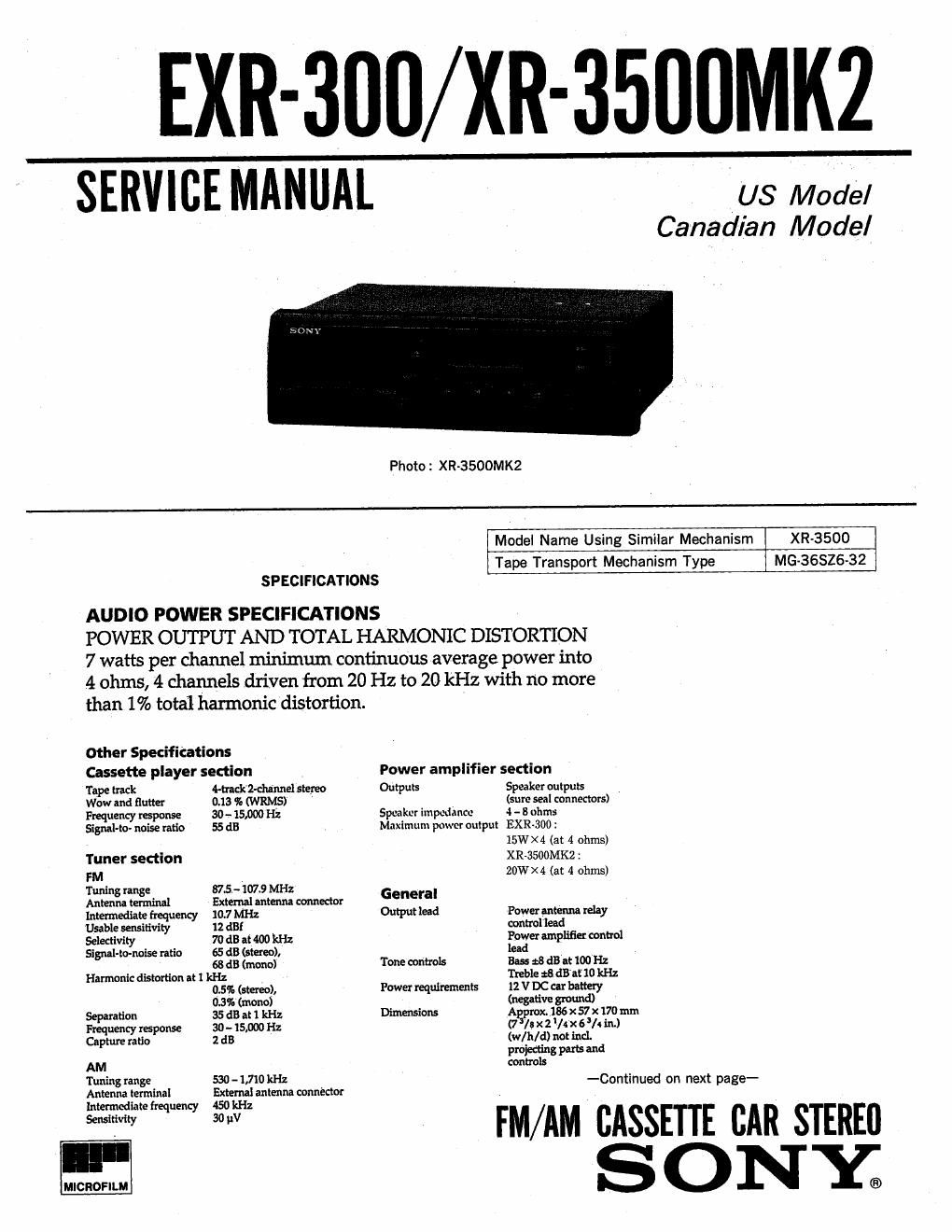
Sony xr 3500 mk2 exr 300
This is the 44 pages manual for sony xr 3500 mk2 exr 300.
Read or download the pdf for free. If you want to contribute, please upload pdfs to audioservicemanuals.wetransfer.com.
Extracted text from sony xr 3500 mk2 exr 300 (Ocr-read)
Page 1
EXR-300/XR-3500MK2
SERVICE MANUAL
[US Modal
Canadian Model
Photo : XR-3500MK2
Model Name Using Similar Mechanism
XR-3500
Tape Transport Mechanism Type
MG-BGSZ6-32
SPECIFICATIONS
AUDIO POWER SPECIFICATIONS
POWER OUTPUT AND TOTAL HARMONIC DISTORTION
7 watts per channel minimum continuous average power into
4 ohms, 4 channels driven from 20 Hz to 20 kHz with no more
than 1% total harmonic distortion.
other Specifications
Cassette player section Power amplifier section
Tape track 4-truk'2-dunnel stereo Outputs Speaker outputs
Wow and flutter 0.13 % (WRMS) (sure seal connectors)
Frequency response 30 -.« 15,000 Hz Speaker impedance 4 - 8 ohms
Signal-to- noise ratio 55 (13 Maximum power output EXR-300 :
15W X 4 (at 4 ohms)
Tuner section XR-asooMKz :
FM 20W X 4 (at 4 ohms)
Tunin range 87.5.- 1073 MHz
Antenia terminal External antenna oonnector General
Intermediate frequency 107 MHz Output lead Power antenm relay
Usablo sensitivity 12 dB! nontrol lead
Selectivity 70 dB at 400 kHz Power amplifier control
Signal-tombs ratio 65 dB (stereo), lead . _
68 dB (mono) Tone controls Bass 2:8 dB at 100 Hz
Harmonic distortion at] kHz Treble fidBaE 10 kHz
0.5% (stereo), Power requirements 12 V DC car battery
03% (mono) (negative ground)
Separation 35 dB at 1 kHz Dimensions Agra-ox. 186 x 57 x 170 mm
Frequency response 30 - 15,000 Hz (7 I! x z /4 x 63/. in.)
Capture ratio 2 d3 (w/lt/d) not incl.
projecting parts and
AM controls
Tuning range 530 - 1,710 kHz V -Continued on next pa ge-
Antenna IeI-minal External antenna connector
Intermediate frequency 450 kHz
30 IIV
Sensitivity
MICROFILM
FM/AM CASSETTE CAR STEREII
S O N Y;
Page 2
, Mmmtlngdhmndon ApproxlexsaxISSmm TABLE OF CONTENTS
Uquz'laxélun.)
(w/h/d) not Incl.d
figural» o ) 1. GENERAL
Mm A i 1 -
Supplied I Pm! I), fl 3" Button Locations .................................. 3
momma utl Setting the Clock .................................. 3
Front panel use (1) .
. . . Cassette Player Operation .................. .A
Mini. Md 1 i mmsublmmdmxmm Radio Reception .................................... 4
Other Functions ... .'. ............................... 5
connections ....... I .........................
Notes on Chip Component Replacement 2. DISASSEMBLY
- Never reuse a disconnected chip component. V ' ' 2-1. Cover. . . . . . . . ....................... L ....... 8
. Notice that the minus side of a tantalum capacitor may be 22 Sub Panel Assy __________________________________ 8
damaged by heat. ' .
2-3. Mechanism Deck Block .......................... 9
2-4. Main Board ...................................... 9
3. MECHANICAL ADJUSTMENTS .................. 10
4. ELECTRICAL ADJUSTMENTS
Deck Section ...........................
Tuner Section .................................... 11
5. DIAGRAMS
5-1. 10 Pin Description .............................. 14
5-2. Printed Wiring Boards-Main Section- .......... 16
5-3. Schematic Diagram-Main Section- ............ 19
5-4. Printed Wiring Board
*Panel Section (EXR-300) .................... 23
5-5. Schematic Diagram-Panel Section (EXRv300)-- . .25
5-6. Printed Wiring Board
-Panel Section (KR-3500MK2)- .............. 27
5-7. Schematic Diagram I
-PaneI Section (XR-3500MK2)- ................ 29
G. EXPLODED VIEWS
6-]. Chassis Section .................................. 34
6-2. Front Panel Section (EXR<300) . . 35
6-3. Front Panel Section (XR-S500MK2) .............. 36
6-4. Mechanism Section (1) ............. 37
6-5. Mechanism Section (2) .......................... 38
7. ELECTRICAL PARTS LIST ...................... 39