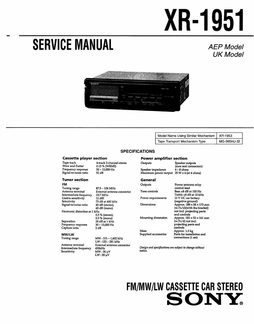
Sony xr 1951 service manual
This is the 30 pages manual for sony xr 1951 service manual.
Read or download the pdf for free. If you want to contribute, please upload pdfs to audioservicemanuals.wetransfer.com.
Extracted text from sony xr 1951 service manual (Ocr-read)
Page 1
SERVICE MANUAL
XR-1951
AEP Model
UK Model
Model Name Using Similar Mechanism XR-1953
Tape Transport Mechanism Type MG-3GSHJ»32
SPECIFICATIONS
Cassette player section Power amplifier section
Tape track 4-track 2-channel stereo Outputs Speaker outputs
Wow and flutter 0.13 % (WRMS) (sure seal connectors)
Frequency response 50 - 15,000 Hz Speaker impedance 4 -- 8 ohms
Signaltomoise ratio 52 dB Maximum power output 5 W X 4 (at 4 ohms)
Tuner section General
FM Outputs Power antenna relay
Tuning range 87.5 - 108 MHz control lead
Antenna terminal External antenna connector Tone EOHCYOIS 335$ 28 dB at 100 Hz
Intermediate frequency 10.7 MHz Treble :8 dB at 10 kHz
Usable sensitivity 12 dBf Power requirements 12 V DC car battery
Selectivity 75 dB at 400 kHz (nesauve grow-d)
Signal-tynoise rafio so dB (stereo), Dimensions Approx. 188 x 58 x 173 mm
65 dB (mono) (w/h/d)(with the bracket)
Harmonic distortion at 1 kHz not incl. projecting pars
05 % (stereo), and controls
03 0/. (mono) Mounting dimension Approx. 182 x 53 x 161 mm
Separation 28 dB at 1 kHz (W( h/ {1) not ind
Frequency response 30 - 15,000 Hz P10194318 Pm and
Capture ratio 2 dB controls
Mass Approx. 1.3 kg
MW/LW Supplied accessorim Pars for installation and
Tuning range MW : 531 - 1,602 kHz WWW" (1 38*)
LW : 153 - 281 kHz
Antenna terminal External antenna connector _ , . . .
Intermediate frequency 450% Design and specifications are subject to change unthoul
Sensitivity MW : 30 V "0"
LW : 35 V
FM/MW/LW CASSETTE CAR STEREO
SONY.
Page 2
CAUTION
Danger of explosion il battery is incorrectly replaced.
Replace only with the same or equivalent type recommended by the
equipment manufacturer.
Discard used batteries according to manufactures instructions.
ADVARSEL!
Lithiumbattcri»Eksplosionsfare ved fejlagtig handtering.
Udskiftning ma kun ske med baueri af samme fabrikat og type.
Lever det brugte batteri tilhage til leverandaren.
ADVARSEL
Eksplosjonslare ved teilaktig skifte av hatteri.
Benytt samme batteritype eller en tilsvarende type anbefalt av
apparatfabrikamen.
Brukte battericr kasseres i henhold til fabrikantens instruksjoner.
VARNING
Explosionstara vid felaktigt batteribyte.
Anvand samma batterityp cller en likvardig typ som rekommenderas
av apparattillver'karen.
Kassera anvant batteri enligt gallande toreskrifter.
VAROITUS
Paristo voi rajamaa, jos so on virheellisesti asennettu.
Vaihda paristo ainoastaan laitevalmistajan suosittelemaan tyyppiin.
Havita kayt/etty paristo valmistajan ohjeiden mukaisesti.
Notes on Chip Component Replacement
I Never reuse a disconnected chip component.
0 Notice that the minus side of a tantalum capacitor may be dam-
aged by heat.
2-2.
2-3.
2-4.
2-5.
TABLE OF CONTENTS
GENERAL
Location of controls
Cassette Player
Radio
Other Functions ..
Additional Information . .
Connections ......................................................................
QAANWU)
DISASSEMBLV
Cover
Front Panel .
MD Block
Heat Sink . .
Main Board ................................................................. l
olexooooo
MECHANICAL ADJUSTMENTS .............................. ll
ELECTRICAL ADJUSTMENTS
Deck Section ..
Tuner Section .
DIAGRAMS
Printed Wiring Boards
Schematic Diagram
EXPLODED VIEWS
Front Panel Section
Chassis Section...
Mechanism Deck ectron ..
Mechanism Deck Section 2..
ELECTRICAL PARTS LIST ...................................... 31