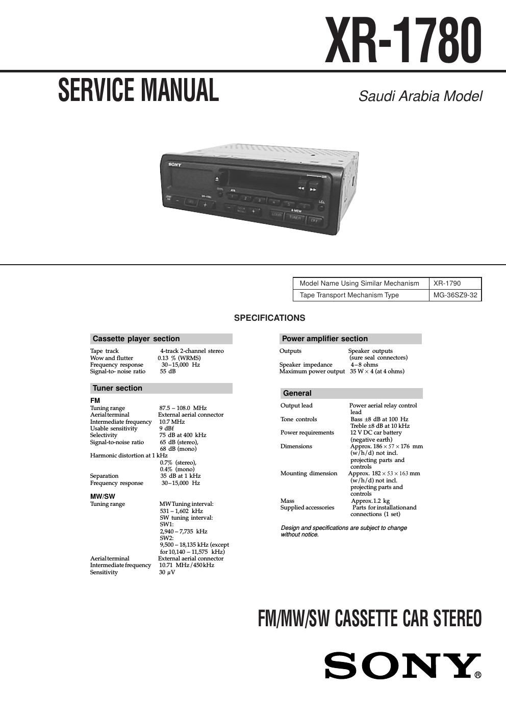
Sony xr 1780 service manual
This is the 34 pages manual for sony xr 1780 service manual.
Read or download the pdf for free. If you want to contribute, please upload pdfs to audioservicemanuals.wetransfer.com.
Extracted text from sony xr 1780 service manual (Ocr-read)
Page 1
2 TABLE OF CONTENTS 1. GENERAL Location of Controls ....................................................... 3 Setting the Clock ............................................................. 3 Installation ....................................................................... 4 Connections ..................................................................... 5 2. DISASSEMBLY ......................................................... 7 3. MECHANICAL ADJUSTMENTS ....................... 11 4. ELECTRICAL ADJUSTMENTS Tape Deck Section .......................................................... 11 Tuner Section .................................................................. 12 5. DIAGRAMS 5-1. Note for Printed Wiring Boards and Schematic Diagrams ....................................................... 15 5-2. Printed Wiring Board – MAIN Board – ........................ 17 5-3. Schematic Diagram – MAIN Board (1/2) – ................... 18 5-4. Schematic Diagram – MAIN Board (2/2) – ................... 19 5-5. Printed Wiring Board – CONTROL Board – ................ 20 5-6. Schematic Diagram – CONTROL Board – ................... 20 5-7. IC Pin Function Description ........................................... 21 6. EXPLODED VIEWS ................................................ 23 7. ELECTRICAL PARTS LIST ............................... 29Flexible Circuit Board Repairing - Keep the temperature of the soldering iron around 270 ˚C dur- ing repairing. - Do not touch the soldering iron on the same conductor of the circuit board (within 3 times). - Be careful not to apply force on the conductor when soldering or unsoldering. Notes on chip component replacement - Never reuse a disconnected chip component. - Notice that the minus side of a tantalum capacitor may be dam- aged by heat.
Page 2
3 SECTION 1 GENERAL This section is extracted from instruction manual. 4 GB Location of controls 7LCL (local seek) button 7 8 (volume/bass/treble/ balance/fader control) buttons 5, 8 9SEEK/MANU button 7 0LOUD (loudness) button 8 qaTUNER/A MEM (radio on - band select/ automatic memory) button 5, 7, 8 qsOFF button Refer to the pages listed for further details. 1Display window 2SEL (control mode select) button 5, 8 3DSPL (display mode change/time set) button 5 4Z (eject) button 6 5During radio reception: Preset number buttons 8 During tape playback: ATA1 ATA (Automatic Tuner Activation) button 6 6m/M (fast-winding)/DIR (tape transport direction change) buttons 6 DSPL ATA SEEK MANU LCL A MEMDIR 2 13 6 4 5 XR-1780 SEL TUNER OFF LOUD The clock activates. 6 Press the DSPL button. NoteThe clock cannot be set unless the power is turned on. Set the clock after you turn on the radio, or during tape playback. Setting the clock The clock has a 12-hour digital indication. Example: To set the clock to 10:08 1 Turn the ignition switch of your car on. 2 Press the TUNER button, or insert a cassette to turn the unit on. 3 Display the time. (Press the DSPL button during unit operation.) 4 Press the DSPL button for more than two seconds. Set the hour. 5 Press the SEL button. Set the minute. (to go backward)(to go forward) The hour digits blinks. The minute digits blink. (to go backward)(to go forward)