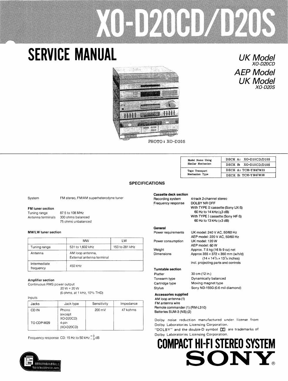
Sony xo d 20 cd service manual
This is the 32 pages manual for sony xo d 20 cd service manual.
Read or download the pdf for free. If you want to contribute, please upload pdfs to audioservicemanuals.wetransfer.com.
Extracted text from sony xo d 20 cd service manual (Ocr-read)
Page 2
XO-D20CD/ D205
TABLE OF CONTENTS
Section Title Page
Specification................ ..... 1
Ceramic Filters (CM and CF2) ...... . . . . 2
Location and Function of
PartsandControls 3
SECTIONl.DIAGRAMS...............5
1-1. Printed Wiring Board (1)
(1unersection).............5
1-2. Schematic Diagrams (1)
(Tuner section) ...... . . . . . . . . 7
1-3. Printed Wiring Board (2)
(Amp and power-supply section) . . . . . 11
1-4. Schematic Diagrams (2)
(Amp and power-supply section) . . . . . 15
SECTION 2. EXPLODED VIEWS . . . . . ...... 20
SECTION 3. ELECTRICAL PARTS LIST . . . . . 25
MODEL IDENTIFICATION
- Specification Label - XO.D20CD
XO-DZOS
SONY; MODEL N0. m
STEREO DECK RECEIVER SYSTEM
I
UK model: 240V~ 50/60 Hz 120 W
AEP model: 220V~ 50/60 Hz 60 W
SAFETY-RELATED COMPONENT WARNING]!
COMPONENTS IDENTIFIED BY MARK A 0R DOTTED
LINE WITH MARK A ON THE SCHEMATIC DIAGRAMS
AND IN THE PARTS LIST ARE CRITICAL TO SAFE
OPERATION. REPLACE THESE COMPONENTS WITH
SONY PARTS WHOSE PART NUMBERS APPEAR AS
SHOWN IN THIS MANUAL OR IN SUPPLEMENTS PUB.
LISHED BY SONY.
Note-1 on Ceramic Filter (CFlfll, 102) Replacement
and Diode D364, 365 Connection.
This set employs two ceramic filters (CF101, 102)
which should have the same color marking to
Therefore FM IF
offset adjmtment by diodes (D364, 365) connection is
identify their center frequency.
necessary to match the center frequency of the
ceramic filters used with FM intermediate frequency.
Color marking
CF101, 102
0: connect
X: not connect
D364, 365
connection FM intermedi-
ate frequency
Color Center i're- A 8 MHz)
mark quenCY (Mu) (D364) (D365)
Ceramic ti 1 ter
White 10.750 0 X 10.750
Red 10.700 X X 10.700
Black 10.650 X 0 10.650
FM intermediate frequency is determined by the
three types as shown above. Ceramic filters of
same center frequency, i.e., of same color coding
should be used for CF101 and CF102.
When replacing the ceramic filters, perform the FM
Discriminator Adjustment.
Note-2 on xo-DZOS's Main Mounting Board Re-
placement
The spare parts of the XO-D2DS's main mounting
board can be supplied by the substitute pars of an
XO-DZOCDs main mounting board. When the
XO-DZOCD is used for the XO-DZOS, therefore, its
parts should be replaced partially.
(1) Remove
the connector
ICJ13) for xo-Dzocn.
_I*L_I_
Front side If
(2) Install the pin jock
{or XO-DZIICD.
Ref. Pam N0.
OJ 1-501-801-21