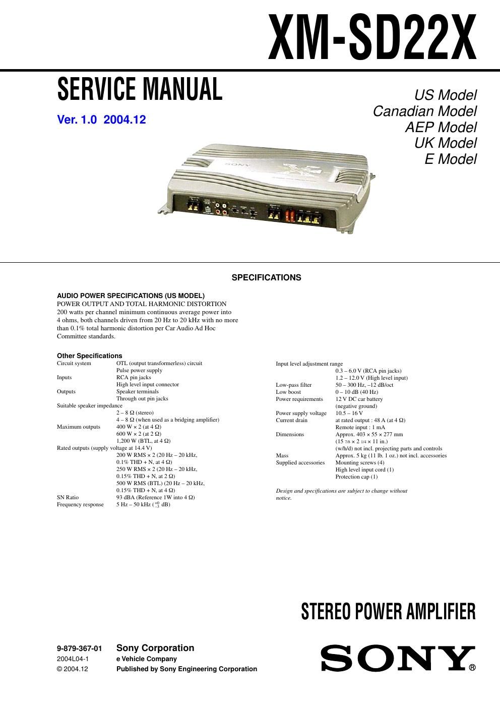
Sony xmsd 22 x service manual
This is the 24 pages manual for sony xmsd 22 x service manual.
Read or download the pdf for free. If you want to contribute, please upload pdfs to audioservicemanuals.wetransfer.com.
Extracted text from sony xmsd 22 x service manual (Ocr-read)
Page 1
2 TABLE OF CONTENTS 1. GENERAL Location and Function of Controls .......................................... 3 Connections ........................................................................\ ..... 4 2. DISASSEMBLY 2-1. Bottom Plate ........................................................................\ 7 2-2. Main Board Section ............................................................ 8 2-3. Main Board ........................................................................\ . 8 2-4. LED Board ........................................................................\ .. 9 3. ELECTRICAL ADJUSTMENT .................................... 10 4. DIAGRAMS 4-1. Block Diagram .................................................................. 11 4-2. Schematic Diagram –Main Section (1/2)– ........................ 12 4-3. Schematic Diagram –Main Section (2/2)– ........................ 13 4-4. Printed Wiring Boards –Main Section– ............................ 14 5. EXPLODED VIEWS 5-1. Heat Sink (Main) Section .................................................. 16 5-2. Main Board Section .......................................................... 17 6. ELECTRICAL PARTS LIST ......................................... 18 Notes on Chip Component Replacement - Never reuse a disconnected chip component. - Notice that the minus side of a tantalum capacitor may be dam- aged by heat. SAFETY-RELATED COMPONENT WARNING!! COMPONENTS IDENTIFIED BY MARK 0 OR DOTTED LINE WITH MARK 0 ON THE SCHEMATIC DIAGRAMS AND IN THE PARTS LIST ARE CRITICAL TO SAFE OPERATION. REPLACE THESE COMPONENTS WITH SONY PARTS WHOSE PA RT NUMBERS APPEAR AS SHOWN IN THIS MANUAL OR IN SUPPLEMENTS PUBLISHED BY SONY. ATTENTION AU COMPOSANT AYANT RAPPORT À LA SÉCURITÉ!! LES COMPOSANTS IDENTIFIÉS PAR UNE MARQUE 0 SUR LES DIAGRAMMES SCHÉMATIQUES ET LA LISTE DES PIÈCES SONT CRITIQUES POUR LA SÉCURITÉ DE FONCTIONNEMENT. NE REMPLACER CES COMPOSANTS QUE PAR DES PIÈCES SONY DONT LES NUMÉROS SONT DONNÉS DANS CE MANUEL OU DANS LES SUPPLÉMENTS PUBLIÉS PAR SONY. XM-SD22X Note for Replacement of FET Change the both channels of FETs at the output stage. If one or both parts in the following combination is broken, the service kit should be ordered. Service kit part No. Q108, 110, 112 X-3383-027-1 Q208, 210, 212 Q109, 111, 113X-3383-028-1 Q209, 211, 213
Page 2
3 XM-SD22X SECTION 1 GENERAL This section is extracted from instruction manual. Features-Maximum power output of 400 W per channel (at 4 Ω). -This unit can be used as a bridging amplifier with a maximum output of 1,200 W. -Direct connection can be made with the speaker output of your car audio unit if it is not equipped with a line output (High level input connection). -Built-in variable LPF (Low-pass filter) and low boost circuit. -Dual mode connection possible for a multi- speaker system. -Protection circuit. -Pulse power supply* for stable, regulated output power. *Pulse power supply This unit has a built-in power regulator which converts the power supplied by the DC 12 V car battery into high speed pulses using a semiconductor switch. These pulses are stepped up by the built-in pulse transformer and separated into both positive and negative power supplies before being converted into direct current again. This light weight power supply system provides a highly efficient power supply with a low impedance output. Caractéristiques-Puissance de sortie maximale de 400 W par canal (à 4 Ω). -Cet appareil peut être utilisé comme amplificateur en pont dune sortie maximale de 1 200 W. -Une connexion directe est possible avec la sortie haut-parleur de votre autoradio si celle-ci nest pas équipée dune sortie de ligne (connexion dentrée haut niveau). -Filtre passe-bas (LPF) intégré et circuit damplification de basses fréquences. -Double mode de connexion possible au moyen dun système à plusieurs haut-parleurs. -Circuit de protection. -Alimentation électrique par impulsions* pour une puissance de sortie stable, régulée. *Alimentation électrique par impulsions Cet appareil est équipé dun régulateur de puissance intégré qui convertit la puissance fournie par une batterie de voiture de 12 V CC en impulsions ultra-rapides au moyen dun commutateur à semi-conducteur. Ces impulsions sont amplifiées par le transformateur dimpulsions intégré et séparées en alimentation positive et négative avant dêtre reconverties en courant continu. Ce système dalimentation de faible poids assure une alimentation électrique très efficace pour une sortie dimpédance faible. Circuit Diagram Schéma du circuit Low boost Amplification de basses fréquences Frequency/Fréquence dB Frequency/Fréquence dB Cut-off frequency (LPF) Fréquence de coupure (LPF) PROTECTOR FILTER OFFLPF LEVEL LOW BOOST (40Hz) 0 +10dB 6 0.3V 2 4 5.5 0.5 60 50 300Hz170 110 260 10 10 0 40 100 1k 10 0 -10 -20 -30 -40 -50 -60 -70 -80 10 100 1k 50Hz 170Hz300Hz LEVEL LPF NormalAMP Power Lch LEVEL InvertedAMP Power Rch BTL Lch Rch(BTL.) LOW BOOST LOW BOOST Hz Hz Location and Function of Controls 1PROTECTOR indicator When the PROTECTOR is activated, the indicator lights up in red. When the PROTECTOR is activated refer to the Troubleshooting Guide. 2LEVEL adjustment control The input level can be adjusted with this control. Turn it in the clockwise direction when the output level of the car audio unit seems low. 3LOW BOOST level control Turn this control to boost the frequencies around 40 Hz to a maximum of 10 dB. 4Cut-off frequency adjustment control Sets the cut-off frequency (50 – 300 Hz) for the low-pass filter. 5FILTER selector switch When the switch is in the LPF position, the filter is set to low-pass. Emplacement et fonction des commandes 1Indicateur PROTECTOR Lorsque PROTECTOR est activé, lindicateur sallume en rouge. Lorsque PROTECTOR est activé, reportez- vous au guide de dépannage. 2Commande de réglage LEVEL Le niveau dentrée peut se régler avec cette commande. Tournez cette commande dans le sens des aiguilles dune montre lorsque le niveau de sortie de lautoradio semble faible. 3Commande de niveau LOW BOOST Tournez cette commande pour amplifier les fréquences autour de 40 Hz jusquà un maximum de 10 dB. 4Commandes de réglage de la fréquence de coupure Permet de régler la fréquence de coupure (50 – 300 Hz) pour le filtre passe-bas. 5Sélecteur FILTER Lorsque le sélecteur est en position LPF, le filtre est réglé sur passe-bas.