Sony xec 500 service manual

This is the 13 pages manual for sony xec 500 service manual.
Read or download the pdf for free. If you want to contribute, please upload pdfs to audioservicemanuals.wetransfer.com.

Page: 1 / 13
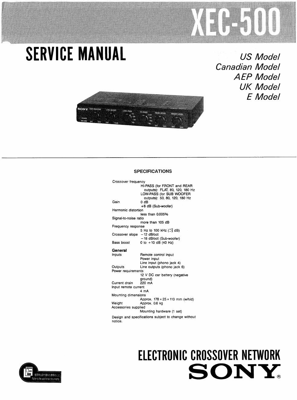
sony xec 500 service manual

Extracted text from sony xec 500 service manual (Ocr-read)


Page 1

SERVICE MANUAL us Model

Canadian Model
AEP Model

UK Model

E Model

SPECIFICATIONS

Crossover Irequency
Hl-PASS (for FFIONT and HEAR
outputs): FLAT. BO, 120, 180 Hz
LOW»PASS (for SUB WOOFEFI
outputs): 50, 80, 120, 180 Hz
Gain 0 US
+5 :15 (Sub-woofer)
Harmonic distortion
less than 0.005%
Signal more than 105 dB
Frequency response
5 Hz to 100 kHz (:3 dB)
Crossover slope -12 dBIoct
-18 dE/oct (Sub-woofer)
Bass boost 0 to +10 dB (40 Hz)

General
Inputs Remote control input
Power input
Line input (phone jack 4)
Outputs Line outputs (phone jack 6)

Power requirements
12 V DC car battery (negative
ground)
Current drain 220 mA
Input remote current
4 mA
Mounting dimensions
Approx. 178 x 25 x 110 mm (win/d)
Weight Approx. 0.6 kg
Accessories supplied
Mounting hardware (1 set)

Design and specifications subject to change without
notice

ELECTRONIC canssuvrn NETWflRK
SONY;

Page 2

XEC-500

- Linear phase filteis (Bessel function type)
realize natural and equal sound levels in and
around the passband frequency.

- The sound balance of front and rear can be
adjusted without affecting a sub«woofer
sound.

0 40H: low boost control allows dynamic bass
reproduction

'Linear phase filters (Bessel function type) :
Most of the channel dividers currently available
employ flat response filters (Butterworth type). The
group delay characteristic of this type of filters is
much worse than that of the linear phase filters.
and this causes transient distortion in the audio

signals at each filter's crossover lrequency, To _

reduce that distortion and to mm mm sound. Crossover Paint Response Curve
linear phase filters (Bessel tunction type) are used

lor the XEGSOO.

40 100 Hz
FREQUENCY

ow-imss

no 100 1K Hz
FREQUENCY

TABLE OF CONTENTS

1 . GENERAL

Location and Function of controls 3
Some Examples of System Configuration - ~ 4
Connections 5
Installation 7
2. DIAGRAMS

2-1, Block Diagram ---- 8
2-2, Printed Wiring Board 9
2-3. Schematic Diagram ---------------------- 11
3. EXPLODED VIEW ...................... 13
4. ELECTRICAL PARTS LIST ------------ 14