Sony wx 7700 mdx service manual

This is the 106 pages manual for sony wx 7700 mdx service manual.
Read or download the pdf for free. If you want to contribute, please upload pdfs to audioservicemanuals.wetransfer.com.

Page: 1 / 106
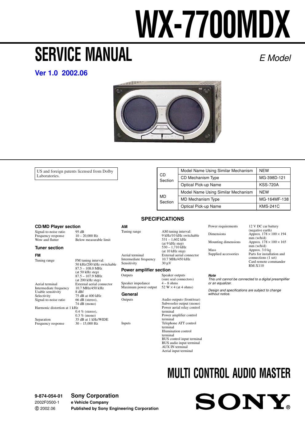
sony wx 7700 mdx service manual

Extracted text from sony wx 7700 mdx service manual (Ocr-read)


Page 2

3 WX-7700MDX 1. SERVICING NOTES ................................................ 4 2. GENERAL Location of Controls....................................................... 5 3. DISASSEMBLY 3-1. Disassembly Flow........................................................... 10 3-2. Front P anel Section......................................................... 11 3-3. DISPLAY Boar d............................................................. 11 3-4. Chassis (T) Section......................................................... 12 3-5. MD Mechanism Deck (MG-164MF-138)...................... 12 3-6. POWER Board, Chassis (T) Assy.................................. 13 3-7. Heat Sink ........................................................................\ . 13 3-8. SERVO (MD) Board....................................................... 14 3-9. MD Cov er Assy............................................................... 14 3-10. Float Block ...................................................................... 15 3-11. LO Motor Assy................................................................ 15 3-12. Lever Assy (LE).............................................................. 16 3-13. Holder Assy ..................................................................... 16 3-14. Chucking ARM Assy...................................................... 17 3-15. Optical Pick-up (KMS-241C)......................................... 17 3-16. SL Motor Assy (SLED) (M902)/ SP Motor Assy (SPINDLE) (M901)............................... 18 3-17. CD Mechanism Deck (MG-398D-121).......................... 18 3-18. Motor Assy (Front Panel Open/Close) (M640) .............. 19 3-19. MAIN Board, Chassis (B) Assy..................................... 19 3-20. Brack et (MAIN).............................................................. 20 3-21. Chassis (T388) Assy....................................................... 20 3-22. Sensor (CD) Board.......................................................... 21 3-23. Servo Board, LO Motor SUB Assy (Loading) (M103) ........................................................................\ ..... 21 3-24. ARM Roller Assy, LO AD Board.................................... 22 3-25. Floating Bloc k Assy........................................................ 22 3-26. Optical Pick-up (KSS-720A), Sled Motor Assy (M101) ........................................................................\ ..... 23 4. ASSEMBLY 4-1. Assembly of ARM (L/R) Assy....................................... 23 5. DIAGRAMS 5-1. Block Diagram – CD SERVO Section –....................... 24 5-2. Block Diagram – MD SERVO Section –...................... 25 5-3. Block Diagram – MAIN Section –................................ 26 5-4. Block Diagram – DISPLAY/BUS CONTR OL Section –........................ 27 5-5. Block Diagram – POWER SUPPLY Section –............. 28 5-6. Note for Printed Wiring Boards and Schematic Diagrams ....................................................... 29 5-7. Printed Wiring Boards – CD Section (1/2) –................ 30 5-8. Printed Wiring Board – CD Section (2/2) –.................. 31 5-9. Schematic Diagram – CD Section –.............................. 32 5-10. Printed Wiring Boards – MD Section –......................... 33 5-11. Schematic Diagram – MD Section (1/2) –.................... 34 5-12. Schematic Diagram – MD Section (2/2) –.................... 35 5-13. Printed Wiring Boards – MAIN Board (Component Side) –.............................. 36 5-14. Printed Wiring Board – MAIN Board (Conductor Side) –................................ 37 5-15. Schematic Diagram – MAIN Board (1/4) –................... 38 5-16. Schematic Diagram – MAIN Board (2/4) –................... 39 5-17. Schematic Diagram – MAIN Board (3/4) –................... 40 5-18. Schematic Diagram – MAIN Board (4/4) –................... 41 5-19. Printed Wiring Board – DISPLAY Board (Component Side) – ........................ 42 5-20. Printed Wiring Boards – DISPLAY Board (Conductor Side) – .......................... 43 5-21. Schematic Diagram – DISPLAY Board (1/2) –............. 44 5-22. Schematic Diagram – DISPLAY Board (2/2) –............. 45 5-23. Printed Wiring Board – KEY Board (Component Side) –................................. 46 5-24. Printed Wiring Board – KEY Board (Conductor Side) –................................... 47 5-25. Schematic Diagram – KEY Board –............................. 48 5-26. Schematic Diagram – SUB/POWER Boards –............. 49 5-27. Printed Wiring Board – POWER Board (Component Side) – ........................... 50 5-28. Printed Wiring Boards – POWER Board (Conductor Side)/SUB Board –...................................... 51 5-29. IC Pin Function Description........................................... 63 6. EXPLODED VIEWS 6-1. MAIN Section ................................................................. 78 6-2. SUB Panel SUB Assy Section........................................ 79 6-3. Front P anel Section......................................................... 80 6-4. Front Panel SUB Section................................................ 81 6-5. DISPLAY Boar d Section................................................ 82 6-6. Chassis (T) Assy Section................................................ 83 6-7. Chassis (B) Assy Section-1............................................. 84 6-8. Chassis (B) Assy Section-2............................................. 85 6-9. MD Mechanism Deck Section-1 (MG-164MF-138) ..... 86 6-10. MD Mechanism Deck Section-2 (MG-164MF-138) ..... 87 6-11. MD Mechanism Deck Section-3 (MG-164MF-138) ..... 88 6-12. CD Mechanism Deck Section-1 (MG-398D-121)......... 89 6-13. CD Mechanism Deck Section-2 (MG-398D-121)......... 90 6-14. CD Mechanism Deck Section-3 (MG-398D-121)......... 91 7. ELECTRICAL PARTS LIST ............................... 92 TABLE OF CONTENTS