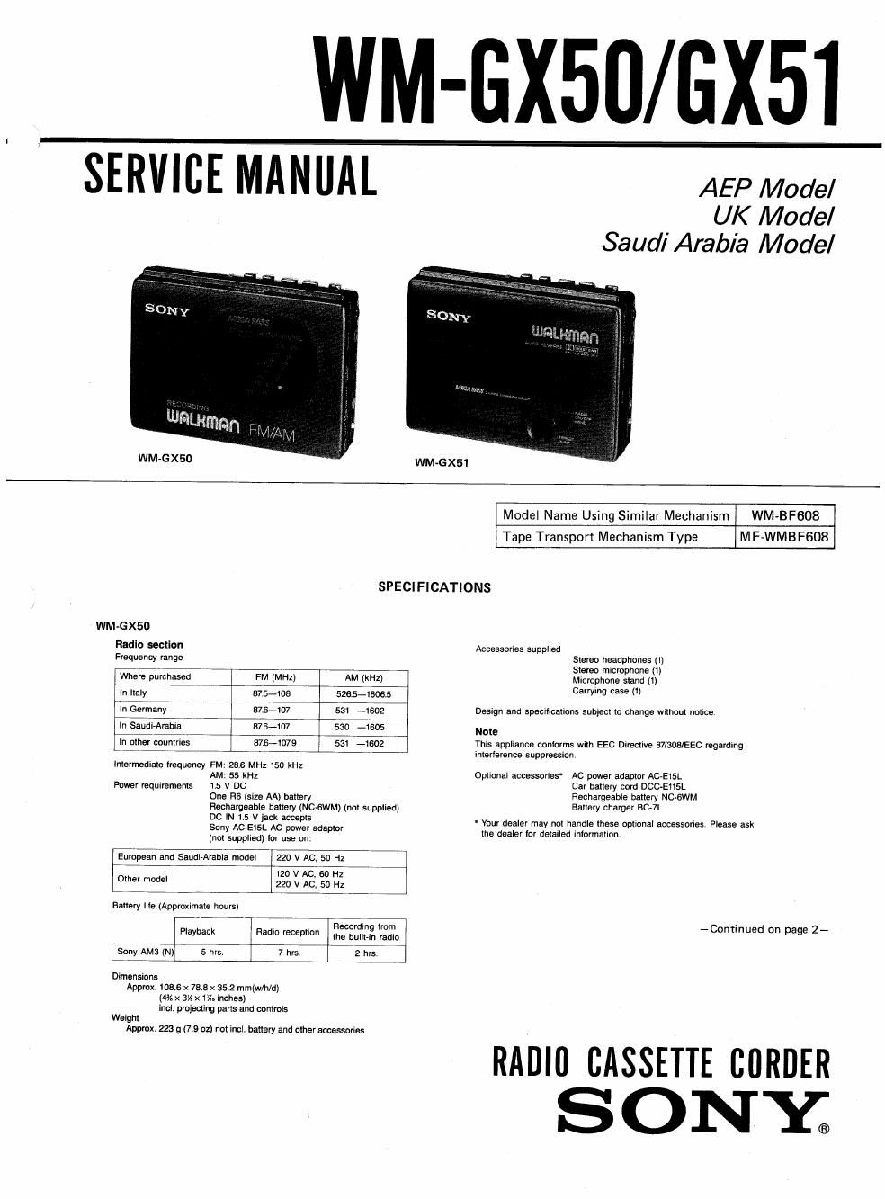
Sony wm pg 50 service manual
This is the 36 pages manual for sony wm pg 50 service manual.
Read or download the pdf for free. If you want to contribute, please upload pdfs to audioservicemanuals.wetransfer.com.
Extracted text from sony wm pg 50 service manual (Ocr-read)
Page 1
WM-GX50/GX51
SERVICE MANUAL AEPMode/
UK Model
Saudi Arabia Model
WM-GX50 WM-GXSI
Model Name Using Similar Mechanism WM-BF608
Tape Transport Mechanism Type M F-WMBF608
SPECIFICATIONS
WM-GX50
Radio section Accessories supplied
Frequency range Stereo headphones (1)
Stereo microphone rt)
Where purchased FM (MHz) AM (kHz) Microphone stand (1)
in Italy 575405 5265-16065 cawm case (1)
in Germany 375-107 sax M1502 Desagn and specifications subject la change without nolrce.
tn SaudirArabia 816-07 530 -1805 Note
In other countries 3754073 531 -1602 This appliance conrorrns wnh EEC Directive B7/308IEEC regarding
lnrarierence suppression
lniennealate troquency FM: 28.6 MHz 150 kHz
AM: 55 kHz Optional accessones' AC power adaptur Ac-EisL
Power requirements 1.5 v DC Car battery cord DCC-EVISL
One as (5.29 AA) battery Rechargeable battery NC-sWM
Hechargeable battery (NC-GWM) (not supprred) Ballefy chaser BC»7L
DC IN 15 v jack accepts . You, dame, m r
y not handle these oplrcnal accessories. Please ask
SW 5 9 PM SW" the oealer tor deialled intermation.
(not supplied) for use on:
European and Saudi-Arabia model 220 v Ac, so Hz
120 v Ac, so Hz
Other model 220 v AC. 50 Hz
Battery tire (Approximate hours)
Playback Radio reception :fggflg'ggo -C°"Y'"U9d 0" Page 2-
Sony AMs (N) 5 hrs, 1 hrs. 2 hrs.
Dimensions
Approx. 108.6 x 78.8 x 35.2 mm(wlh/d)
(4% x 3y. x m. incheel
Incl. projecting park and controls
Wslghrl
Approx. 223 g (7.9 or) not Incl. binary and other accessones
RADIO CASSETTE BORDER
SON Y;
Page 2
WM-GX50/GX51
WM-GX51
Radio section
Frequency range
Whale purchased FM (MHz) AM (kHz)
In Italy 875-109 522-1611
In Germany 875-106 531-1602
In Saudi-Arabia 375-108 53-18%
In other countries 575-108 531-1802
Intermediate frequency
FM: 10.75 MHZ
AM: 450 kHz
Antenna
FM: Headphones cord antenna
AM: Built-in lerr'me bar antenna
neoetding omlon
Recording system
4-track Z-channel stem
Input
Microphone Input (tiered minijock)
(PLUG IN PONER) sensitivity 077 mV (-60 dB) lor loner
impedance microphone
Tape player section and general
Frequency response (DOLEV NR om
40 Hl-IS kHz (with the PB E0 selector set to NORMAL 0i
CrOz/MEIAL)
Output
Headphones (stereo mlnliack)
Load Impedance 8-3000
Power output
5nlW + 5mWatDCeperalio-r.1en
Power requlrements
15 V Dc
Rechargeable battery
One as (size AA) battery
DC [N 15 V jack accepts;
0 Sony w-E15L Ac power adaptor (not aupplled)
available in the United Kingdom bf use on 240 V AC,
50 Hz
available In other European countries lor use on 220 v
AC. 50 Hz
available in other countries lor use on 100-120 V Ac or
22D-240VAB,500I60H2
. Sony occansi (riot supplied) lor use with l2 v car
battery
Battery life (hours)
Battery Playback Radio Recording from
receptlon the builtein radio
Sony mam) Approx,5 Apprat.7 Approx.2
For maximum perlormanoe we recommend the use of alkaline
batteries.
Dimensions
Approx. toes x m x 35.2 mm(th/d)
143/, x all. x 17/5inches)
incl. projecting parts and controls
Weight
Approx. 226 g (5.0 oz) not Incl. battery and other
accessories
Accessories supplied
Lithium battery (CRZOIG) 11) Miuppnone (I)
Microphone stand (1) Stereo headphones (I)
Carrying case it)
Design and specifications subject to change without notloe.
Not.
This appliance commie: with EEC Directive Swain/EEC
regarding interlerenoe suppression.
omnollooenorles
Ac power adaptor PC-EISL
Battery charger BC-7L
Rechargeable binary NO-GWM,
Ger battery cord Doc-EllsL
Lithium battery CRZDIB
Your dealer may run handle some at the above listed optional
accessories Please ask the dealer ltrr demiled information.
TABLE OF CONTENTS
Section Title FEE
SECTION 1. GENERAL
Parts Identification Nomenclature (WM-6X50) --------- 3
Parts Identification Nomenclature (WM-6X51) '-
Service Notes ------
SECTION 2. DISASSEMBLY
2-1. Cabinet (Rear) Assy Removal --------------------- 6
2-2. Flexible Board Removal --------------
2-3. Tuner Board Removal (WM-6X50) --------
Tuner Board Removal (VIM-6X51) -------------------- 7
SECTION 3. ADJUSTMENTS
3-1. Mechanical Measurements ~ - ~
3-2. Electrical Adjustments
SECTION 4. DIAGRAMS
441. Block Diagram (Audio Section) ------------------ 15
Block Diagram (Tuner Section WM-GXED) -- > 17
Block Diagram (Tuner Section VIM-(2X51) -- -- 19
4-2. Printed Wiring Boards (Audio Section) -- Zl
. 25
4-3. Schematic Diagram (Audio Section) ---- ~
4-4. Schematic Diagram (Tuner Section VIM-6X51) -- 30
4-5. Printed Wiring Boards (Tuner Section VIM-6X51) 33
4-6. Printed Wiring Boards (Tuner Section VIM-6X50) - ,. 35
4-7. Schematic Diagram (Tuner Section WM-GXSD) ------- 37
SECTION 5. EXPLODED VIEWS
5-1. Cabinet Section-1
5-2. Cabinet Section-2 -- -
5-3. Mechanism Section-l (MF-WMBFGDB) ~
5-4. Mechanism Section-2 (MF-WMBFBDE) ~- ----- - 42
SECTION 6. ELECTRICAL PARTS LIST """"""" 43
SAFETY-R E LATED COMPONENT WARNING"
COMPONENTS IDENTIFIED BV MARK A 0R DOTTED
LINE WITH MARK A ON THE SCHEMATIC DIAGRAMS
AND IN THE PARTS LIST ARE CRITICAL TO SAFE
OPERATION. REPLACE THESE COMPONENTS WITH
SONY PARTS WHOSE PART NUMBERS APPEAR AS
SHOWN IN THIS MANUAL OR IN SUPPLEMENTS PUB-
LISHED BY SONY.
WARNING I!
ADVARSEL!
Lithiumbatteri ~ Eksplosionsfare
Udskiftning m3 kun foretages
af en sagkyndig, og som
beskrevet i servicemanualen.
LITHIUM BATTERY
SHOULD ONLY BE CHANGED BY TECHNICAL
PERSONNEL. THERE IS A RISK FOR EXPLOSION
AT A WRONG HANDLING.