Sony wm gx 90 service manual

This is the 40 pages manual for sony wm gx 90 service manual.
Read or download the pdf for free. If you want to contribute, please upload pdfs to audioservicemanuals.wetransfer.com.

Page: 1 / 40
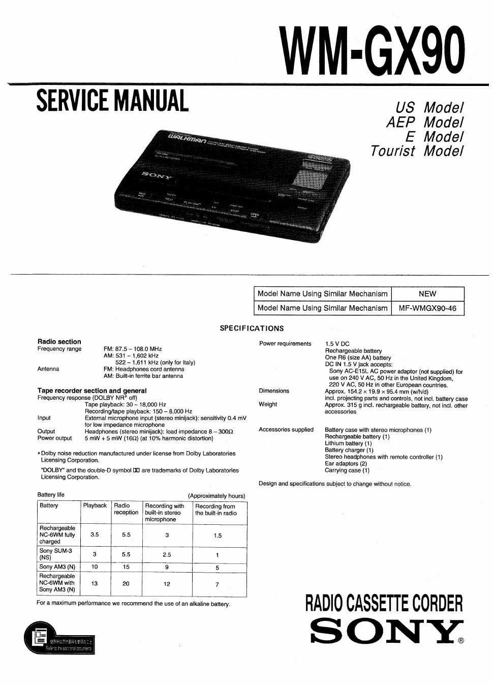
sony wm gx 90 service manual

Extracted text from sony wm gx 90 service manual (Ocr-read)


Page 1

WM-GX90

SERVICE MANUAL us Model

AEP Model
E Model
Tourist Model

Model Name Using Similar Mechanism NEW

Model Name Using Similar Mechanism MF-WMGX90-46

SPECIFICATIONS

Radio section Power requirements 1.5 V DC
Frequency range FM: 37.5 - 108.0 MHz Rechargeable battery
AM: 531 - 1.602 kHz One R6 (size AA) battery
522 - 1,611 kHz (Only for Hair) DC IN 15 v jack accepts:
Antenna FM: Headphones cord antenna Sony AC-EISL AC power adaptor (not supplied) Ior
AM: Built-in lerrite bar antenna use on 240 V AC, 50 Hz in ma United Kingdom,
220 V AC, 50 Hz in other European countries.
Tape recorder section and general Dimensions Approx. 154.2 x 193 x 95.4 mm (w/h/d)
Frequency response (DOLBY NR otl) incl. projecting parts and controls. not incl. battery case
Tape playback: 30 - 18,000 Hz Weight Approx. 315 9 incl. rechargeable battery. not incl. other
Recording/tape playback: 150 - 8.000 H2 accessories
Input External microphone input (stereo minijack): sensitivity 0.4 mV
for low im edance microphone I V I .
Output Headphones (stereo minijack): load impedance 8 - 3009 Accessories SUWIed Battery case With 519 microphones (1)
Power output 5 mW + 5 mW (too) (at 10% harmonic distortion) FIefha'geable we II)
Lithium battery (1)

Battery charger (1)

Stereo headphones with remote controller (1)
Ear adaptors (2)

DOLBY' and the double-D symbol a] are trademarks of Dolby Laboratories Carrying case (1)

Licensing Corporation.

*Dolby noise reduction manufactured under license from Dolby Laboratories
Licensing Corporation.

Design and specifications subject to change without notice.

Battery life (Approximately hours)
Battery Playback Radio Recording with Recording lrom
reception built-in stereo the built-in radio
microphone
Rechargeable
NC-GWM IuIIy 35 55 3 15
charged
Sony SUM-3
(NS) 3 5,5 25 1
Sony AM3 (N) 10 15 9 5
Rechargeable
NC-SWM with 13 20 12 7
Sony AMS (N)

we mm RADIO CASSETTE CORDEH
S O N Y;

Page 2

WM-GXQO

Section Lfle
Specification ----------------
1. SERVICE POSITION-
2. GENERAL
2-1. Parts Identification-
. DISASSEMBLY --------
. MECHANICAL ADJUSTMENT~~ --
. ELECTRICAL ADJUSTMENTS ---------------------------------- 6
. DIAGRAMS
6-1. Block Diagrams ------------------------
6-2. Semiconductor Lead Layouts ------
53. Printed Wiring board - 1(CONTROL SECTION)
6-4. Schematic Diagram - 1(CONTROL SECTION) --
6-5. Printed Wiring board - 2(MAIN SECTION)"-
6-6. Schematic Diagram - 2 MAIN(AUDIO) ~-
6-7. Schematic Diagram - 3 MAIN(TUNER) --
6-8.1C Block Diagrams ...............................

TABLE OF CONTENTS

GUI-bu

7. EXPLODED VIEWS
7-1.MAIN SECTION-1m
7-2. MAIN SECTION-2
7-3. MD SECTION]
7-4, MD SECTION-2

Flexible Circuit Board Repairing

0 Keep the temperature of the soldering iron around 270 C during
repairing.

0 Do not touch the soldering iron on the same conductor of the
circuit board (within 3 times).

- Be careful not to apply force on the conductor when soldering or
unsoldering.

Notes on chip component replacement

0 Never reuse a disconnected chip component.

0 Notice that the minus side of a tantalum capacitor may be
damaged by heat.

8.ELECTRICAL PARTS LIST --------------------------------------- 39
SECTION 1 MCL FLEXIBLE BOARD CONNECTOR
SERVICE POSITION FLEXIBLE BOARD

This set detects reel rotation by PH3OI (photo sensor).

Reel rotation cannot be detected when the MAIN board is removed,
because PH301 is mounted on the MAIN board. As a result, the
auto-off circuit and tape end detection will misoperate. And, up and
down of head and main of playback circuit cannot operate when the
MAIN board is removed, because 8306 (play switch) is mounted
on the MAIN board. (8306 is linked to on and off the plunger
solenoid)

Therefore, operation check of the mechanism deck and voltage
check can be performed by the method shown below,

Furthennore, the display of LCD701 (frequency board display
only) cannot be shown while the main board is removed (figure 1).
However, the tuner section activates normally.

(Perform this adjustment after adjusting the frequency and remov-
ing the MCL flexible board when adjusting the tracking and
f-cover.)

Note : Handle the MCL flexible board with care when setting the
service position (figure 1) .

FF/REW mode

1)Apply the square wave signal to the PH3OI. (figure 2)
2)Tum ON the CLOSE switch on $708 board (Control board) ,
3)Press the V) or {4 key.

PLAY mode

1)Apply the square wave signal to the PH3OI. (figure 2)
2)Tum ON the CDOSE switch on $708 board (Control board) .
3)Fast-forward (FF) or rewind (REW) once and then STOP.
4)Press the V key.

5)Tum on $306 a few seconds later.


MAIN BOARD

Fig. 1
MAIN BOARD -- SIDE B -
PHao1
a $306
\ it
/
SQUARE WAVE @
20H: OdB (1V)

I_..-.
Hg 2 AF osc