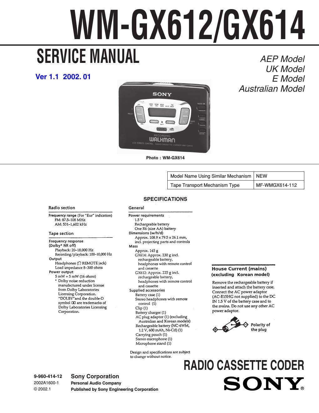
Sony wm gx 614 service manual

This is the 32 pages manual for sony wm gx 614 service manual.
Read or download the pdf for free. If you want to contribute, please upload pdfs to audioservicemanuals.wetransfer.com.

Page: 1 / 32
sony wm gx 614 service manual

Extracted text from sony wm gx 614 service manual (Ocr-read)


Page 1

- 2 - Section Title Page SECTION 1. SERVICE NOTE ................................. 3 SECTION 2. GENERAL .......................................... 5 SECTION 3. DISASSEMBLY 3-1. Cassette Lid ASSY and Case ASSY ................................. 7 3-2. Bracket ASSY and Cassette Holder ASSY ....................... 7 3-3. Tuner Board ....................................................................... 8 3-4. Main Board ......................................................................... 8 SECTION 4. MECHANICAL ADJUSTMENT .......... 9 SECTION 5. ELECTRICAL ADJUSTMENT ........... 9 SECTION 6. DIAGRAMS 6-1. IC Pin Functions IC501 BA3641FV REC AMP ......................................... 11 IC701 MSM63120B System Control .............................. 11 IC702 SMC62L3A LCD Drive ....................................... 13 6-2. Printed Wiring Board - Tuner Section - ..................... 14 6-3. Schematic Diagram - Tuner Section - ........................ 17 6-4. Schematic Diagram - Main Section - ......................... 21 6-5. Printed Wiring Board - Main Section - ...................... 25 6-6. IC Block Diagrams .......................................................... 29 SECTION 7. EXPLODED VIEWS 7-1. Case Section ..................................................................... 33 7-2. Main Board Section ......................................................... 34 7-3. Mechanism Section (MF-WMGX614-112) ..................... 35 SECTION 8. ELECTRICAL PARTS LIST ............. 36TABLE OF CONTENTS SAFETY-RELATED COMPONENT WARNING !! COMPONENTS IDENTIFIED BY MARK ! OR DOTTED LINE WITH MARK ! ON THE SCHEMATIC DIAGRAMS AND IN THE PARTS LIST ARE CRITICAL TO SAFE OPERATION. REPLACE THESE COMPONENTS WITH SONY PARTS WHOSE PART NUMBERS APPEAR AS SHOWN IN THIS MANUAL OR IN SUPPLEMENTS PUBLISHED BY SONY. Notes on chip component replacement - Never reuse a disconnected chip component. - Notice that the minus side of a tantalum capacitor may be damaged by heat. Flexible Circuit Board Repairing - Keep the temperature of the soldering iron around 270 °C during repairing. - Do not touch the soldering iron on the same conductor of the circuit board (within 3 times). - Be careful not to apply force on the conductor when solder- ing or unsoldering.

Page 2

- 3 - [MAIN Board] - Side A - - Side B - [Lever (FR SW)] SECTION 1 SERVICE NOTE [Service Mode] Mode which enables the mechanism to be operated with the MAIN board opened. Photo sensor PH701 mounted on the MAIN board is used to detect rotaion of the reels. Because it is mounted on the MAIN board, when the MAIN board is being removed, rotation of the reels cannot be detected and the auto-off/tape-end detector circuit does not operate correctly. F/R switch (S701) is also mounted on the MAIN board. Therefore, without the MAIN board, the head cannnot be placed in playback position, and power cannot be supplied to the circuitry of the playback system. When the MAIN board is being removed, follow the procedures below, in order to check operation of the mechanisms of the tape deck and to check voltages supplied to each circuit. 1. Setting 1) Refer to Disassembly and remove the cabinet and open the MAIN board. 2) Connect the MAIN board to the motor and plunger using a jumper wire. Use Extension tool (1-769-143-11)) (one set 10 tools) to make connection simple. 3) Short-circuit the service mode land (BP2) by soldering. 4) Apply a square wave signal to TP20. (See the figure on the right.) 5) Supply 1.5V to the battery terminals (+) and (–) using a DC power supply. 2. Preset State This state must be set to set the PLAY, FF, and REW modes. 1) Check that the lever (FR SW) is at the center and F/R switch (S701) is at the center. If not, set the preset state as follows. 2) Move the F/R switch (S701) according to the side faced by the lever (FR SW). 3) Turn OFF the DC power supply switch once and then turn it ON again so that the lever (FR SW) can be moved. Move the F/R switch (S701) according to this timing and set to the center. 3. FF REW Mode 1) Set the preset state and press the FF switch and REW switch. 4. PLAY Mode 1) Set the preset state. 2) Press the ~ switch. The lever (FR SW) will move to the F side once and then to the R side. Move the F/R switch (S701) according to this timing to set the PLAY (R side) mode. Press the ~ switch another time and move the F/R switch (S701) according to the movement of the lever (FR SW) to set the PLAY (F side) mode. Note 1 : If the above cannot be performed, start again from preset. Note 2 : Use the remote control ~, &, FF, and REW switches as much as possible. If the remote control is not available, do not touch S703 to S706 with the hand and use something with a round tip to press them. F side R sideCenter Lever (FR SW) CenterF side R sideS701 F/R SWITCH (FWD n STOP n REV) PH701S702 (HOLDER SWITCH) S714 (C HOLD) S707 (RADIO ON BAND) S711 (TUNING +)S712 (TUNING –) S713 (ENTER)Connect to plunger S703 (RADIO OFF p) S704 (REPEAT œ) Battery Terminal (–) S709 (SET)S710 (MENU)S706 (AMS REW PRESET –) Service mode landS705 (AMS FF PRESET +)Connect to motor Battery Terminal (+) TP20 AF OSCILLATORSQUARE WAVE (SINE WAVE) 10Hz 3.5 dB (1.5V)