Sony wm fx 833
This is the 22 pages manual for sony wm fx 833.
Read or download the pdf for free. If you want to contribute, please upload pdfs to audioservicemanuals.wetransfer.com.
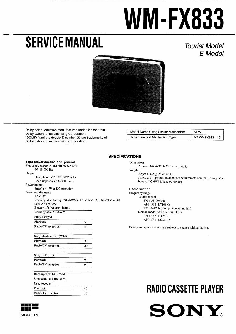
Extracted text from sony wm fx 833 (Ocr-read)
Page 1
WM-FX_833
SERVICE MANUAL
Tourist Model
E Model
Dolby noise reduction manufactured under license from
Dolby Laboratories Licensing Corporation
DOLBY and the double-D symbol [1] are trademarks of
Dolby Laboratories Licensing Corporation
Model Name Using Similar Machanism NEW
Tape Transport Mechanism Type MT-WMEXeaa-t 12
SPECIFICATIONS
Tape player section and general Dimensions
Frequency response (In NR switch oft) Approx. |08.6x78.4x23,4 mm (w/h/d)
3048.000 Hz Weight
Output Approx. [45 g (Main unit)
Headphones (Q REMOTE jack)
Load impeadance 8-300 ohms
Power output
4mW + 4mW at DC operation
Power requirements
1.5V DC
Rechargeable battery (NC-6WM), 1.2 V. GOOmAh. Nl-Cd One R6
(size AA) battery
Battery life (Approx. hours)
Rechargeable NC-6WM
Fully charged
Playback 9
Radio/TV reception 9
Sony alkaline LR6 (WM)
Playback 33
Radio/T V reception 29
Sony R6P (SR)
Playback 9
Radio/TV reception 9
Rechargeable NC-6WM
Sony alkaline LR6 (WM)
Used together
Playback 40
Radio/1 V reception 36
Approx. 240 g(1ncl. Headphones wuh remote control, Rechargeable
battery NC-oWM. Tape (C-GOHF)
Radio section
Frequency range
Tourist model
FM :7&90MH2
AM : S31-l.7lOkHz
TV : Ir|2ch (Except Korean model)
Korean model (Area setting : Eur)
FM: 87.5-108MH2
AM : SSl-l.602kHz
Design and specifications are subject to change without notice,
RADIO CASSETTE PLAYER
S O N'Y®
Page 2
TABLE OF CONTENTS
Specifications 1
1. GENERAL
Location and Function of Controls ,,,,,,,,,,,,,,,,,,,,,,,,,,,,,,,,, 3
2. SERVICE NOTE .................................................... 5
3. DISASSEMBLY
31. Case Assy Removal
3«2. Audio Board Removal
3-3. Cassette Lid Assy, Tuner Board Removal
3-4, Mechanism Deck Removal iiiiiiiiiiiiiiiiiiii
4. ADJUSTMENTS
4-1. Mechanical Adjustments
4-2. Electrical Adjustments .,
5. EXPLANATION OF ICTERMIANLS.n.......l..n.l.l...i.l. 12
6. DIAGRAMS
6-]. Printed Wiring Boards (Tuner Section) .
6-2. Schematic Diagram (Tuner Section)
6-3. Schematic Diagram (Audio Section) .
6-4. Printed Wiring Boards (Audio Section) .
7. EXPLODED VIEWS
7-1l Cassette Lid. Case Section ........................................ 29
7-2. Audio Board Section ................................................. 30
7-3. Mechanism Deck Section (MT-WMEX633-112).W 31
8. ELECTRICAL PARTS LIST ........................................ 32
Flexlble Circuit Board Repairing
~ Keep the temperature of the soldering iron around 270°C during
repairing.
0 Do not touch the soldering iron on the same conductor of the cir-
cuit board (within 3 times)
- Be careful not to apply force on the conductor when soldering or
unsolderingi
Notes on chip component replacement
0 Never reuse a disconnected chip component.
0 Notice that the minus side of a tantalum capacitor may be dam-
aged by heat