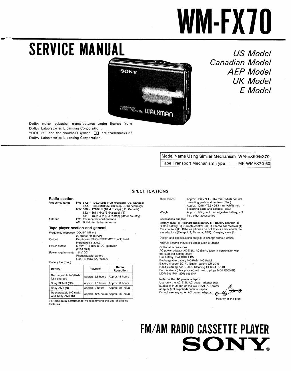
Sony wm fx 70 service manual
This is the 24 pages manual for sony wm fx 70 service manual.
Read or download the pdf for free. If you want to contribute, please upload pdfs to audioservicemanuals.wetransfer.com.
Extracted text from sony wm fx 70 service manual (Ocr-read)
Page 1
WM-FX'ID
Dolby noise reduction manufactured under license from
Dolby Laboratories Licensing Corporation.
"DOLEY" and the double-D symbol DC] are trademarks of
Dolby Laboratories Licensing Corporation.
US Model
Canadian Model
AEP Model
UK Model
E Model
Model Name Using Similar Mechanism WM-EX60/EX70
Tape Transport Mechanism Type MF-WMFX70«60
SPECIFICATIONS
Radio section
Frequency range FM: 375 - 108.0 MHz(1DO kHz stop) (us, Canada)
875 - 108.0MHz (50kHz step) (other country)
MW: 530 - mom: (10 kHz step) (us, Canada)
522 ~ 1611 kHz (9 kHz step) (m
531 - 1602 kHz (9 kHz step) (Other country)
Antenna FM: Ear receiver cord antenna
AM: Built-In lemle bar antenna
Tape player section and general
Frequency response (00st NR oil)
2048.000 Hz (EIAJ')
Output Earphones (PHONESIREMOTE )ack) load
1mpedance oaoon
5 mw r 5 mW at DC operation
(EN 150)
Power requirements 1.5 V DC
Rechargeable baflery
One R6 (size AA) battery
Power output
Ballery Illa (EIAJ)
Radio
Battery Playback magma
Rechargeable NGGWM
luity charged
Sony SUM-3 (NS)
Sony AM3 (N)
Rechargeable Nosth
Mm SW Am (N) Approx 12.5 hours Approx. 33 hours
Approx. 35 hours Approx 8 hours
Approx, 25 hours Approx, 8 hours
Approx 9 hours Approx. 25 hours
For maximum perlormanca we recommend the use oi alkaline
batteries.
Dimensions Approx, 105 x74 1 x234 mm (w/h/dl noi irtci
projecling pans and controls (EIAJ)
Approx 1088 x 755 x 263 mm (w/h/d) Incl
protecting pans and controls (EIAJ)
Weight Approx, 195 9 incl. rechargeable battery, not
incl. other accessories
Accessories supplied
Battery case (1) Rechargeable battery (1) Battery charger (1)
Button battery (1) Remote control unlltl) stereo ear receiver (1)
Ear adaptors (2) it the earphones do not fit your ears, almch the
ear adaptors (Except us. Canada. AEP), Carrying case (1)
Dwgn and specifications sublet! to change without notice.
- (ElAl) Electric industries Wlallon oi Japan
Optional accessories
Ac power adaptor Ac.Et5L, AC-EtsAL (Use in conjuncllon with
the supplied battery case)
Car battery cord Doc EiisL
Rechargeable battery NCABWM, moswm
Battery charger 507A, Button battery on zote
Head cleaning pen CLH~5. Cleaning kit Km. KK~3|
Ear Iecewers (Heaophpries) with micro plugs MDR-E565MP,
MDR~E557MR MDRVESSSMP
Note on the.Ac power adaptor
Use only the Aoatst Ac power adaptor (not
supplied) in Japan or me ACAElfiAL Ac power
adaptor (not supplied) ouiSIde Japan,
Do not use any other Ac power adaptor.
Polallly oi the plug
FM/AM RADIO CASSETTE PLAYER
SONY;
Page 2
WM-FX7O
TAB LE OF CONTENTS
Section M page
Specifications .................................. 1
1. SERVICING NOTE ..................... 2
2. GENERAL ............................. 3
3. DISASSEMBLY
3-1. Panel Assy, Control Removal ............... 4
3-2. Ornamental Assy, Control Removal --------- 4
4. MECHANICAL ADJUSTMENTS
4-11 Mechanical Adjustment .................... 5
4-2. Electrical Adjustment 5
5. DIAGRAMS
5-1. Tuner Section Block Diagram -------------- 9
5-2. Audio Section Block Diagram -------------- 11
5-3. Audio Section Printed Wiring Boards ~~~~~~~~ 13
5-4. Audio Section Schematic Diagram ---------- 17
5-5. Tuner Section Schematic Diagram ----------- 20
5-6. Tuner Section Printed Wiring Boards -------- 23
s. EXPLODED VIEWS .................... 25
7. ELECTRICAL PARTS LIST ----------- 28
- MAIN Board (side A) -
SQUARE WAVE
OSCILLATOR
@ 20H:
OdB (1 V)
SECTION 1
SERVICING NOTE
This set detects reel rotation by PH701 (photo
sensor). Reel rotation cannot be detected when the
main board is removed, because PH701 is mounted on
the main board. As a result, the auto-off circuit and
tape end detection will misoperate. And, up and down
of head and power supply of playback circuit cannot
operate when the main board is removed, because S
703 (NR switch) is mounted to the main board (S703
is linked to on and off of the plunger solenoid.)
Therefore, operation check of the mechanism deck
and voltage check can be performed by the method
shown below.
FF/REW mode
1) Switch position S703 : STOP (Center)
2) Apply the square wave signal to the PH701.
3) Press the « or » key.
PLAY mode
1) Switch position S703 : STOP (Center)
2) Apply the square wave signal to the PH701.
3) Press the > key.
4) Turn on S703 a few seconds later.
- MAIN Board (side A) -