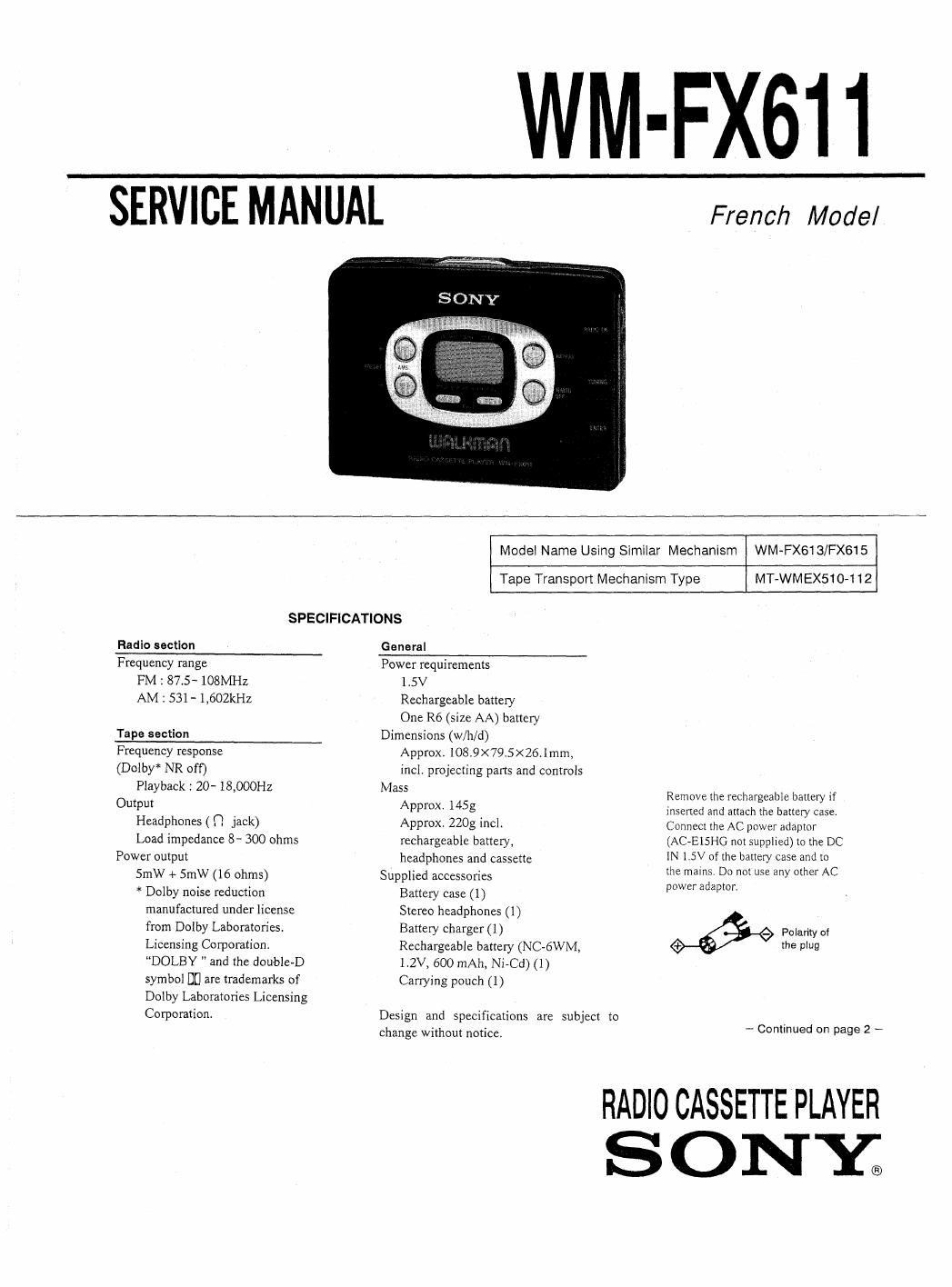
Sony wm fx 611 service manual
This is the 26 pages manual for sony wm fx 611 service manual.
Read or download the pdf for free. If you want to contribute, please upload pdfs to audioservicemanuals.wetransfer.com.
Extracted text from sony wm fx 611 service manual (Ocr-read)
Page 1
WM-FX611
SERVICE MANUAL
French Model
Model Name Using Similar Mechanism WM~FX613/FX615
Tape Transport Mechanism Type MT-WMEX510-112
SPECIFICATIONS
Radio section
General
Frequency range
FM : 875- 108MHz
AM : S31- l,602kHz
Tape section
Frequency response
(Dolby* NR off)
Playback : 20- 18,000Hz
Output
Headphones ( n jack)
Load impedance 8- 300 ohms
Power output
SmW + SmW (l6 ohms)
* Dolby noise reduction
manufactured under license
from Dolby Laboratories
Licensing Corporation,
DOLBY and the double-D
symbol D0 are trademarks of
Dolby Laboratories Licensing
Corporation
Power requirements
1.5V
Rechargeable battery
One R6 (size AA) battery
Dimensions (w/h/d)
Approx. 108.9X79.5><26.lmm,
incl. projecting parts and controls
Mass Remove the rechargeable battery it
Approx. 1453 inserted and attach the battery Case.
Approx. 220g IHCI- Connect the AC power adaptor
rechargeable battery, (AC-EISHG not supplied) to the DC
headphones and cassette IN 1.5V of the battery case and to
the mains Do not use any other AC
Su lied accessories
pp power adaptor.
Battery case (1)
Stereo headphones (1)
Battery charger (I) w Polarity or
Rechargeable battery (NC-6WM, 5 9
1.2V, 600 mAh, Ni-Cd) ( t)
Carrying pouch (1)
Design and specifications are subject to
change without notice, _ Continued on page 2 _
RADIO CASSETTE PLAYER
S 0 NY;
Page 2
Dry Battery
Battery llfo gApprox. hours)
Sony Sony
alkaline R6?
LRo 380) (SR)
Tape playback IS 345
Radio reception 22 7
For maximum performance we recommend
that you use an alkaline battery,
Notes
- Do not charge a dry battery.
- when you do not use the Walkman for a long
time, remove the battery to avoid any damage
caused by battery leakage and subsequent
corrosion.
Rechargeable Battery
1. Insert the rechargeable battery (NCA6WM)
into the charger with correct polarity.
2. Plug in the charger to the mains.
Full charging takes about 2.5 homsl
3. Insert the fully charged battery into the
rechargeable battery com partment.
When to charge the battery
Charge the battery when the BA'IT lamp dims.
You can charge the battery about 300 times
Battery llfe (Approx. hours)
Rechargeable battery gNC-éWM)
Tape playback 5
20 (with Sony
alkaline LR6 156)
Radio reception 7.5
2.8 (with Sony
alkaline LR6 {SO 2
Notes
- Do not tear off the film on the rechargeable
battery.
- Use the Sony NC-oWM rechargeable battery
only with the supplied battery charger or with
the separately sold battery charger for Seny
NC-GWM.
' Do not leave the charger plugged in for more
than 20 hours Overcharging may damage the
rechargeable battery
' The battery charger and the rechargeable
battery may become warm during charging.
but it is not a problem.
TABLE OF CONTENTS
Specifications ............ . ............ . ....... ....... ....... .........1
1, GENERAL .......... . ........ ........ .. ............ ................3
2. SERVICE NOTEwm ........ . ........... ...... ....4
3. DISASSEMBLY
3-ll Bracket Assembly and Cassette Holder Assembly 6
3.2 MainBoardn .......... ..... --6
3.3_ Tunergofld................... ........ .......... ...... ....7
4. MECHANICAL ADJUSTMENT-"m"- .......... ....... ...3
5. ELECTRICAL ADJUSTMENT ............. .. ............. .....g
6. EXPLANATION OF lC TERMINALS ---------- 10
7. DIAGRAMS
7-]. Printed Wiring Boards (Tuner Section) - 13
7-2. Schematic Diagram (Tuner Section) ~~ - 15
7 -3. Schematic Diagram (Main Section) - 19
7-4, Printed Wiring Boards (Main Section) - Z3
EXPLODED VIEWS
8-1. Cabinet and Tuner Board Section - ~ 30
8-2. Main Board Section ..... .......... . 31
8-3. Mechanism Section (MT-WMEXSIO-llZ) ----- '- ------- 32
ELECTRICAL PARTS LIST .......... ....... 33
Flexible Circuit Board Repairing
0
Keep the temperature of the soldering iron around
270°C during repairing.
Do not touch the soldering iron on the same conduc-
tor of the circuit board (within 3 times).
Be careful not to apply force on the conductor, when
soldering or unsolderingr
Notes on chip component replacement
Never reuse a disconnected chip component.
Notice that the minus side of a tantalum capacitor
may be damaged by heat.