Sony wm fx 12 service manual

This is the 8 pages manual for sony wm fx 12 service manual.
Read or download the pdf for free. If you want to contribute, please upload pdfs to audioservicemanuals.wetransfer.com.

Page: 1 / 8
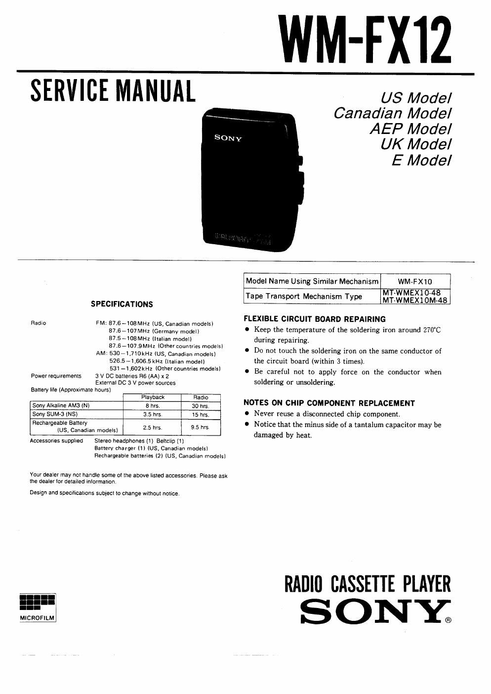
sony wm fx 12 service manual

Extracted text from sony wm fx 12 service manual (Ocr-read)


Page 1

SERVICE MANUAL

WM-FXIZ

US Model
Canadian Model
AEP Modal

UK Model

E Model

SPECIFICATIONS

Radio FM: 876-108MH2 (US, Canadian models)
87.6e107MH2 (Germany model)
87.S-108MH2 (Italian model)
8715-1079 MHz (Other countries models)

AM: 53071.710kHZ (US, Canadian models)
5265 - 1 ,6065 kHz (Italian model)

531 ~l,602kHz (Other countries models)

3 V DC batlenes R6 (AA) x 2

External DC 3 V power sources

Battery Iile (Approximate hours)

Power requiremenls

Playback Radio

Sony Alkaline AMa (N) 8 hrs 30 hrs

Sony SUM-3 (NS) 3.5 hrs 15 hrs,
Hechargeable Battery

(us, Canadian models) 2'5 "5 9'5 '5

Accessories supplied Stereo headphones (1) Beltcliu (1)
Battery charger III (US, Canadian models)

Rechargeable batteries (2) (US, Canadian models!

Your dealer may not handle some 01 the above listed accessories Please ask
the dealer lor detailed mlorrnation.

Design and specifications sublecl to change Wilhoul nolice.

MICROFILM

Model Name Using Similar Mechanism WM-FX10
Tape Transport Mechanism Type lemgéighfiiB

FLEXIBLE CIRCUIT BOARD REPAIRING

Keep the temperature of the soldering iron around 270°C
during repairingi

Do not touch the soldering iron on the same conductor of
the circuit board (within 3 times).

Be careful not to apply force on the conductor when
soldering or unsolderingi

NOTES ON CHIP COMPONENT REPLACEMENT

Never reuse a disconnected chip component,
Notice that the minus side of a tantalum capacitor may be
damaged by heat.

RADIO CASSETTE PLAYER
S 0 NY;

Page 2

WM-FX12
SECTION 1
DISASSEMBLY

Note: Follow the disassembly procedure in the numerical order given.

CABINET (REAR) ASSY

cassette lid assy

precision screw driver
(1.4mm flat-blade)

in to the slit at claw
"% "and release the claw.

' cabinet (rear) assy

9

Remove the cabinet (rear) assy
(Release all claw 0 to (D in
alphabetical order)

MECHANISM DECK AND MAIN BOARD

-\> 1
I lemon mechanism deck and main
LK. board to the direction of the arrow

\front cabinet assy and
cassette lid assy