Sony wm f 2095 service manual

This is the 23 pages manual for sony wm f 2095 service manual.
Read or download the pdf for free. If you want to contribute, please upload pdfs to audioservicemanuals.wetransfer.com.

Page: 1 / 23
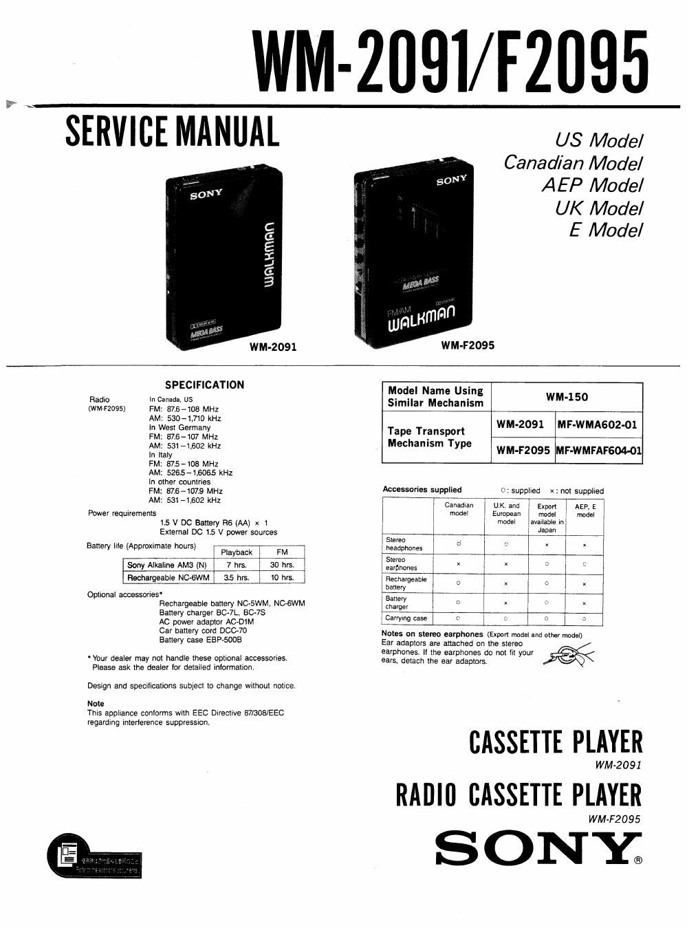
sony wm f 2095 service manual

Extracted text from sony wm f 2095 service manual (Ocr-read)


Page 1

WM-ZDQI/ F2095

SERVICE MANUAL

WM-2091

US Model
Canadian Model
AEP Model

UK Model

E Model

WM-F2095

SPECIFICATION

Radio In Canada, US

(WM12095) FM: 87.6-108 MHZ
AM: 530-IJ10 kHz
In West Germany
FM: 375-107 MHZ
AM: 531 -1.602 kHz
In Italy
FM: 875-103 MHz
AM: 5265-15065 kHz
In other countries
FM: 816-1073 MHZ
AM: 53L -1,602 kHz

Power requirements
1.5 v 00 Battery R6 (AA) x1
External DC 15 V power sources

Batlery lile (Approximate hours) Playback FM

Sony Alkaline AMS (N) 7 hrs. 30 hrs.
Rechargeable NC-GWM 35 hrs. 10 hrs.

Optional accessories
Rechargeable oanery NC-SWM. NOGWM
Battery charger BC-7L. 60-78
AC power adaptor AC-DIM
Car battery cord DOC-70
Battery case ESP-5008

' Your dealer may not handle these optional accessories.
Please ask the dealer for detailed information.

Design and specifications subjecl to change without notice.
Note

This appliance conlorms with EEC Directive B7/308/EEC
regarding interference suppressron.

Model Name Using
Similar Mechanism WM-150

WM-2091 MF-WMAGOZ-Ol
Tape Transport

Mechanism Type

WM-F2095 MF-WMFAF604-01

Accessories supplied 0: supplied x : not supplied
Canadlan UK. and Export AEP. E
model European modal model
model available In
Japan

Stereo 0 E x
headphones ' x
Stereo X x s. n
eamnones
Rechargeaote C X 0
battery
Battery c x o x
charger
Carrying case r,» c 0 2

Notes on stereo earphones (Export model and other model)

Ear adaptors are attached on the stereo
earphones. II the earphones do not fit your
ears, detach the ear adaptors.

CASSETTE PLAYER

WM-2091

RADII] CASSETTE PLAYER

WM-F2095

ONY;

Page 2

WM-2091/F2095

TABLE OF CONTENTS
Section Title Egg
SECTION 1 GENERAL

1-1. Tape Playback...
1-2. Radio Reception

SECTION 2 DISASSEMBLY
2-1. Tuner Unit Removal (WM-F2095) ............ 4

SECTION 3 ADJUSTMENTS
3-1. Mechanical Measurements .................. 5

3-2. Electrical Adjustments ...................... 6

SECTION 4 DIAGRAMS

4-1. Printed Wiring Board ....................... 7
4-2. Schematic Diagram .......................... 9
4-3. IC Block Diagrams .......................... 12

SECTION 5 EXPLODED VIEWS

5-1. Cabinet Section ...... . .13
5-2. Mechanism Section (1) . .14
5-3. Mechanism Section (2) ...................... 15
SECTION 6 ELECTRICAL PARTS LIST .............. 16

Dolby noise reduction manufactured under license from
Dolby Laboratories Licensing Corporation.
"DOLBY" and the double-D symbol DI] are trademarks of
Dolby Laboratories Licensing Corporation.

Notes on battery

0 Remove the battery Mien you will not use the unit
for a long time to prevent damage from battery
leakage and corrosion.

0 The imemal battery is disconnected when you plug
a cord into DC IN 15 V.

0 when the sound becomes unstable, try a new
battery.

External power sources

The following external power sources can be

connected through the DC IN 15 V jack.

. House current using an AGDIM AC power adaptor

- 12 V car battery using a DOC-7O car battery cord

0 Two R20 (size D) batteries using an EBP-EOOB
battery case

The illustration shows the polarity of DC IN 15 V
jack. Use only a power cord having the same

polarity.
69-6-6

SERVICING NOTES

When you are movement check states of removed the audio
board, press the PLAY (>) button, slide on the 5901
(POWER) and 5902 (PLAY) switches,

AUDIO BOARD -Companent side-

5902
(PLA y)

5901 (POWER)

Wide mouth clip

Flexible Circuit Board Repairing

0Keep the temperature of the soldering iron around
270'C during repairing.

ODo not touch the soldering iron on the same con-
ductor of the circuit board (Within 3 times).

U Be careful not to apply force on the conductor when
soldering or unsoldering.

Notes on chip component replacement

0 Never reuse a disconnected chip component.

ONotice that the minus side of a tantalum capacitor
may be damaged by heat.