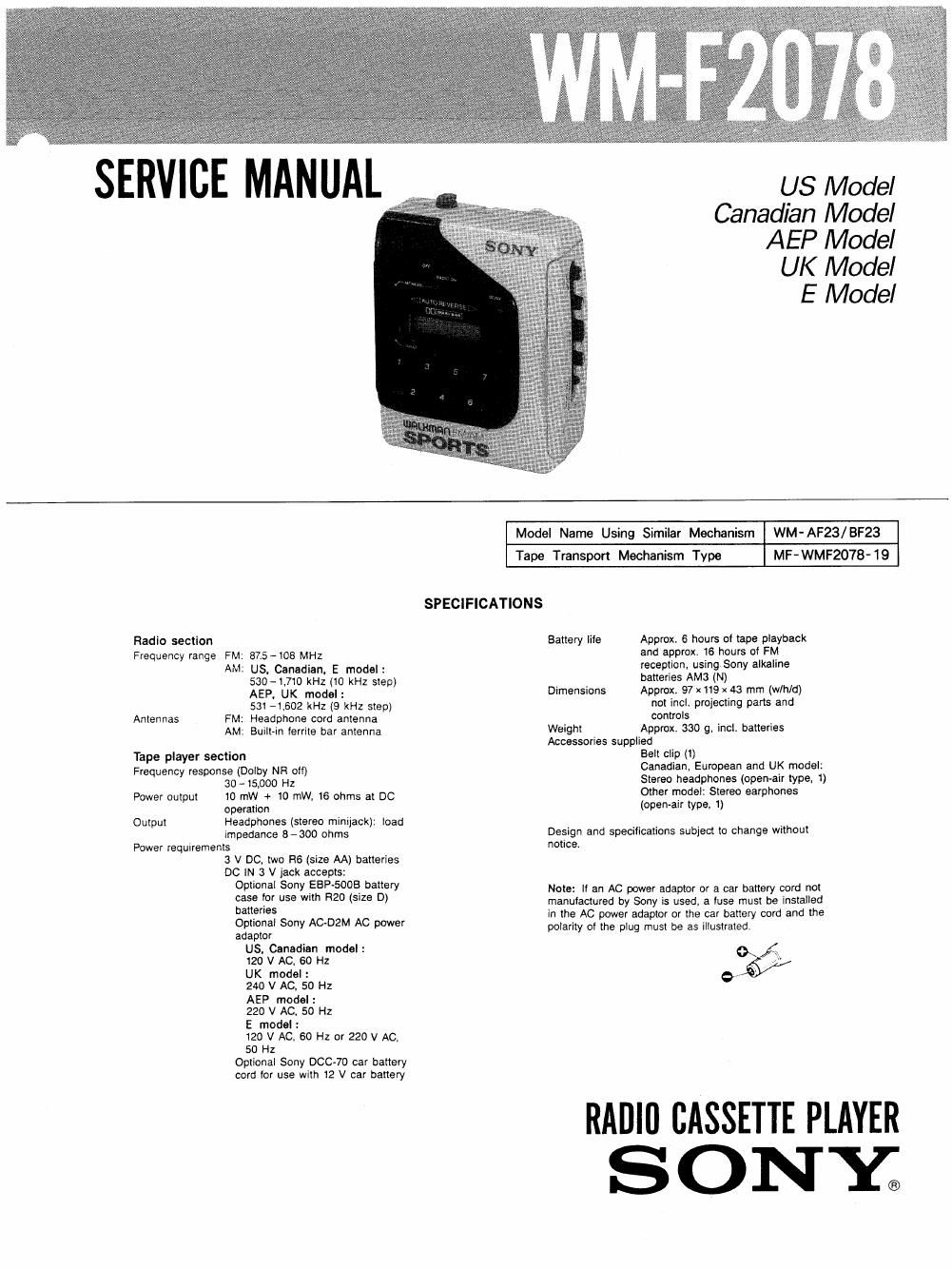
Sony wm f 2078 service manual
This is the 20 pages manual for sony wm f 2078 service manual.
Read or download the pdf for free. If you want to contribute, please upload pdfs to audioservicemanuals.wetransfer.com.
Extracted text from sony wm f 2078 service manual (Ocr-read)
Page 1
SERVICE MANUAL
US Model
Canadian Model
AEP Model
UK Model
E Model
fl .
W
{$91
a
an
35:
9;
he
3%
3%
y no .
. 3:113
'fiéfiaggggwfl
Radio section
Frequency range FM: 875-105 MHz
AM: US. Canadian. E model:
530-l.710 kHz (10 kHz step)
AEP. UK model:
531 -1.602 kHz (9 kHz step)
Antennas FM: Headphone cord antenna
AM: Built-in ferrite bar antenna
Tape player section
Frequency response (Dolby NFt all)
30 - 15,000 Hz
Power output 10 mW + 10 mW, 16 ohms at DC
operation
Output Headphones (stereo minijack): load
impedance 3 - 300 ohms
Power requirements
3 V DC. two H6 (size AA) batteries
DC W 3 V jack accepts:
Optional Sony EBP-SOOB battery
case ior use with R20 (size D)
batteries
Optional Sony AC-DZM AC power
adaptor
US. Canadian model:
120 V AC, 60 Hz
UK model:
240 V AC. 50 HZ
AEP model:
220 V AC, 50 Hz
E model :
120 V AC. 60 Hz or 220 V AC
50 Hz
Optional Sony DOC-70 car battery
cord lor use with 12 V car battery
Model Name Using Similar Mechanism WM-AF23/BF23
MF- WMF2078- 19
Tape Transport Mechanism Type
SPECIFICATIONS
Battery life Approx. 6 hours of tape playback
and approx. 16 hours oi FM
reception. using Sony alkaline
batteries AMa (N)
Dimensions Approx. 97 x 119 x 43 mm (wlh/d)
not incl. projecting parts and
controls
Weight Approx. 330 9, incl. batteries
Accessories supplied
Belt clip (1)
Canadian, European and UK model:
Stereo headphones (open-air type. 1)
Other model: Stereo earphones
(open-air type, 1)
Design and specifications subject to change without
notice.
Note: If an AC power adaptor or a car battery card not
manufactured by Sony is used, a iuse must be installed
in the AC power adaptor or the car battery cord and the
polarity oi the plug must be as illustrated.
9523/
RADIO CASSETTE PLAYER
SONY;
Page 2
WM - F2078
TABLE OF CONTENTS
m m EEK:
Specifications ......................................... 1
1' GENERAL ......................................... 3
2' NOTE ON REPAIR ................................. 6
3. DISASSEMBLY ..................................... 7
4. ADJUSTMENTS
4- 1. Mechanical Adjustments ------------------- a
4-2. Electrical Adjustments --------------------- 8
5. DIAGRAMS
5-]. 1C Block Diagram ......................... 11
5-2, Primed Wiring Board ...................... 12
5-3. Schematic Diagram -Main Section- ----- 15
5-4. Schematic Diagram -Display Section-m- 18
3_ ExpLopEp VIEWS ............................... 20
7. ELECTRICAL PARTS LIST ----------------------- 23
Notes on chIp component replacement
0 Never reuse a disconnected chip component.
I Notice that the minus side of a tantalum capacitor may
be damaged by heat.
FIexlbIe CIrcult Board Repairlng
0 Keep the temperature of the soldering iron around
270 C during repairing.
0 Do not touch the soldering iron on the same conductor
of the circuit board (within 3 times).
0 Be careful not to apply force on the conductor when
soldering or unsoldering.
WARNING !!
ADVARSELI
Lithiumbaiteri-Eksplosionsfare
Udskiftning m5 kun foretages
af en sagkyndig, 0g som
beskrevet i servicemanualen.
LITHIUM BATTERY
SHOULD ONLY BE CHANGED BY TECHNICAL
PERSONNEL THERE IS A RISK FOR EXPLOSION
AT A WRONG HANDLING.
Batteriet mfi kun udskiftes med et batteri af samme
iabrikat og type".
Because of the risk for eXplosion the battery must
be replaced with the same type and manufacture.