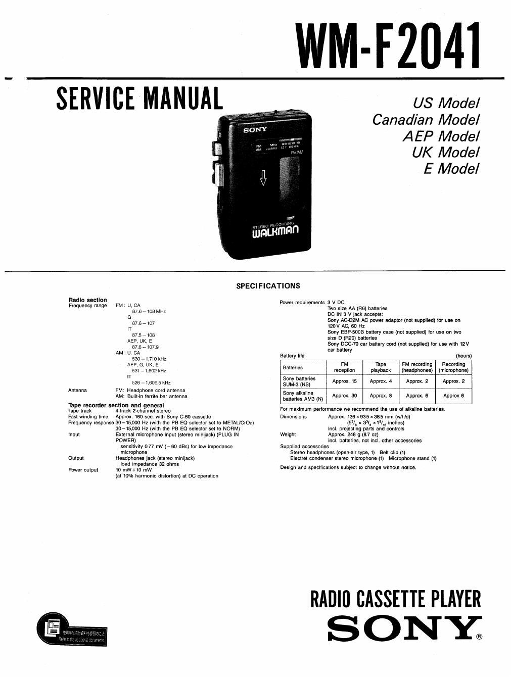
Sony wm f 2041 service manual
This is the 16 pages manual for sony wm f 2041 service manual.
Read or download the pdf for free. If you want to contribute, please upload pdfs to audioservicemanuals.wetransfer.com.
Extracted text from sony wm f 2041 service manual (Ocr-read)
Page 1
WM-FZMI
SERVICE MANUAL
US Model
Canadian Model
AEP Model
UK Model
E Model
SPECIFICATIONS
Radio section
Frequency range FM : U, CA
37.6 - 103 MHZ
G
87.5 - 107
It
87.5 - 108
AEP. UK, E
57.6 - 107.9
AM : U, CA
530 - 1.710 KHz
AEP, G, UK, E
531 - Leoz kHz
lT
526 7 tones kHz
Antenna FM: Headphone cord antenna
AM: Built-in territe bar antenna
Tape recorder section and general
Tape track 4-treck 2-channel stereo
Fast winding llme Approx. 160 sen. wltn Sony c-eo cassette
Frequency response 30-15900 Hz (with the PE E0 selector set to METAUCrOz)
30-15DDO Hz (with the PB EQ selector set to NORM)
input External microphone input (stereo miniialck) (PLUG IN
POWER)
sensitivity 077 mV (-60 655) [Or low impedance
microphone
Output Headphones jack (stereo minijack)
ioad impedance 32 ohms
Power output to mw+1u mW
(at low» harmonic distortioni at DC operation
Power requirements 3 v DC
We size AA (RS) batteries
DC W a v jack aooepls:
Sony Ac-DzM Ac power adaptor (not supplied) tor use on
120V AC, 60 H1
Sony sap-5003 battery case (not supplied) tor use on two
size D (R20) batteries
Sony Doom car batiery cold (not supplied) tor use wilh 12v
car battery
Battery lilo (hours)
B i , FM Tape FM recording Recording
a tense reception playback (headphones) (microphone)
Sony batteries
SUM-3 (NSi
Sony alkaline
batteries AMa (N)
Approx. 15 Approx. 4 Approx. 2 Approx. 2
Approx, so Approx. 5 Approx. 6 Approx 6
For maximum periormanca we reopmmend the use 0' alkaline batteries.
Dimensions Appmx, 136 x 93.5 X 36.5 mm (VI/hid)
(51/H x 33!. x1°lm inches)
incl. projecting parts and controls
Weight Approx. 246 g (5.7 oz)
incl. batteries, not incl. other accessories
Supplied accessories
Stereo headphones (open-air type, 1) Bolt clip (1)
Electret condenser stereo microphone (1) Microphone stand (I)
Design and specifications subject lo change without notice.
RADIU CASSETTE PLAYER
SONY;
Page 2
WM-F2041
Notes on chip component replacement
0
0
Never reuse a disconnected chip component.
Notice that the minus side of a tantalum capacitor may
be damaged by heat.
Flexible Circult Board Repairing
Keep the temperature of the soldering iron around
270°C during repairing.
Do not touch the soldering iron on the same conductor
of the circuit board (within 3 times).
Be careful not to apply force on the conductor when
soldering or unsoldenng.
TABLE OF CONTENTS
Section M Page
Specifications .................................. 1
1. GENERAL
Features
Parts Identification ------------------------
2. ADJUSTMENTS
Mechanical Adjustments -------------------
Electrical Adjustments ~ ------------------
3. DIAGRAMS
3.]. Block Diagram ...........................
3-2. Printed Wiring Boards ---------------------
3-3. Schematic Diagram -----------------------
4. EXPLODED VIEWS
5. ELECTRICAL PARTS LIST
6
9
13