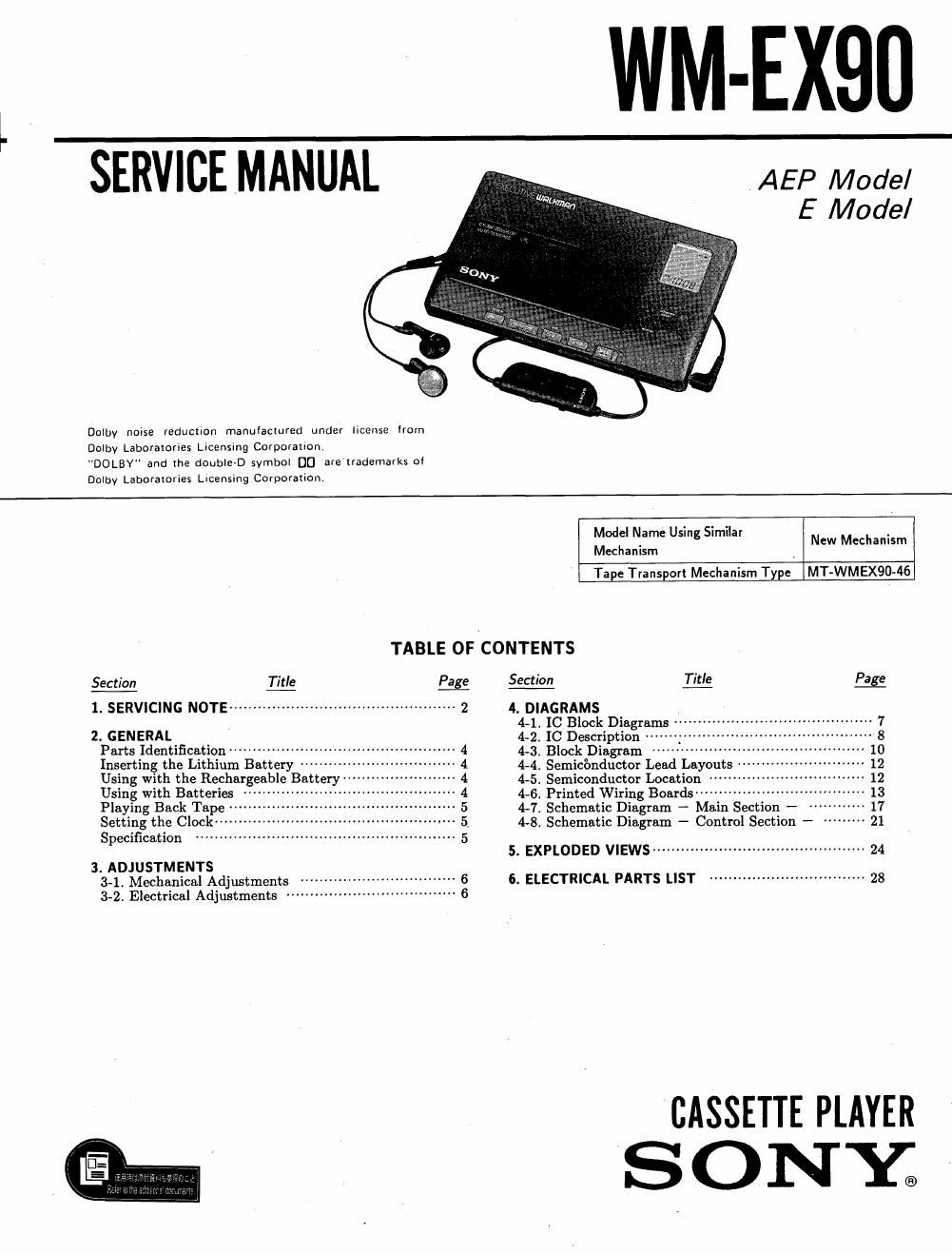
Sony wm ex 90 service manual
This is the 23 pages manual for sony wm ex 90 service manual.
Read or download the pdf for free. If you want to contribute, please upload pdfs to audioservicemanuals.wetransfer.com.
Extracted text from sony wm ex 90 service manual (Ocr-read)
Page 1
WM-EX90 y
AEP Model
E Model
SERVICE MANUAL
Dolby noise reduciion manulaciured under license from
Dolby Laboratories Licensing Corporaiion
"DOLBY" and (he double-D symbol DD are trademarks ol
Dolby Laboraiories Licensing Corporarion.
Model Name Using Similar
Mechanism
Tape Transport Mechanism Type MT»WMEX90A46
New Mechanism
TABLE OF CONTENTS
Section Title Page $_ec_tio_n Litg _P_ag£
l. SERVICING NOTE ------------------------------------------ 2 4. DIAGRAMS ,
4-1. IC Block Diagrams '- 7
2. GENERAL 42. [0 Description .. 8
Parts Identification """"""""" 4 4-3. Block Diagram 10
Inserting the Lithium Battery ~ 4 4-4 Semiconductor Lead Layouts 12
Using with the Rechargeable Battery " 4 4-5. Semiconductor Location 12
Using with Batteries ' " 4 4.6. Printed Wiring Boards ~~~~~~ 13
Playing Back Tape '4 5 4-7i Schematic Diagram - Main Section - 17
Setting the Clock-- 5. 4-8. Schematic Diagram - Control Section - 21
Specification 5
5. EXPLODED VIEWS ............................................. 24
3. ADJUSTMENTS
3-1. Mechanical Adjustments 6. ELECTRICAL PARTS LIST ~~~~~~~~~~~~~~~~~~~~~~~~~~~~~~ 28
3-2. Electrical Adjustments
CASSETTE PLAYER
S ON Y;
Page 2
WM-EX90
SECTION 1
SERVICING NOTE
This set detects reel rotation by PH801 (photo sensor). - Main board (Parts mounted side) -
Reel rotation cannot be detected when the main board is
removed, because PHSO] is mounted on the main board.
As a result, the auto-off circuit and tape and detection will
misoperate. And, up and down of head and power supply
of playback circuit cannot operate when the main board is PHBM
removed, because S306 (HEAD switch) is mounted on the a
main board. (S306 is linked to on and off of the plunger 5306
solenoid on mechanism deck.) .
Therefore, operation check of the mechanism deck and
voltage check can be performed by the method shown
below. H
FF/REW mode
(1) Apply the square wave signal to the PH801 (refer to I
diagram)
(2) Turn on S708(oontrol board) CLOSE switch.
(3) Press the » or « key. Square wave In
ZOHZ AF OSC
PLAY mode 30")
(1) Apply the square wave signal to the PH801 (refer to
diagram)
(2) Turn on S708(control board) CLOSE switch.
(3) Press the » or « key, then press the STOP key.
(4) Press the F key.
(5) Turn on 5306 1 to 1.5 seconds later. (refer to diagram)