Sony wm ex 85 service manual

This is the 29 pages manual for sony wm ex 85 service manual.
Read or download the pdf for free. If you want to contribute, please upload pdfs to audioservicemanuals.wetransfer.com.

Page: 1 / 29
sony wm ex 85 service manual

Extracted text from sony wm ex 85 service manual (Ocr-read)


Page 1

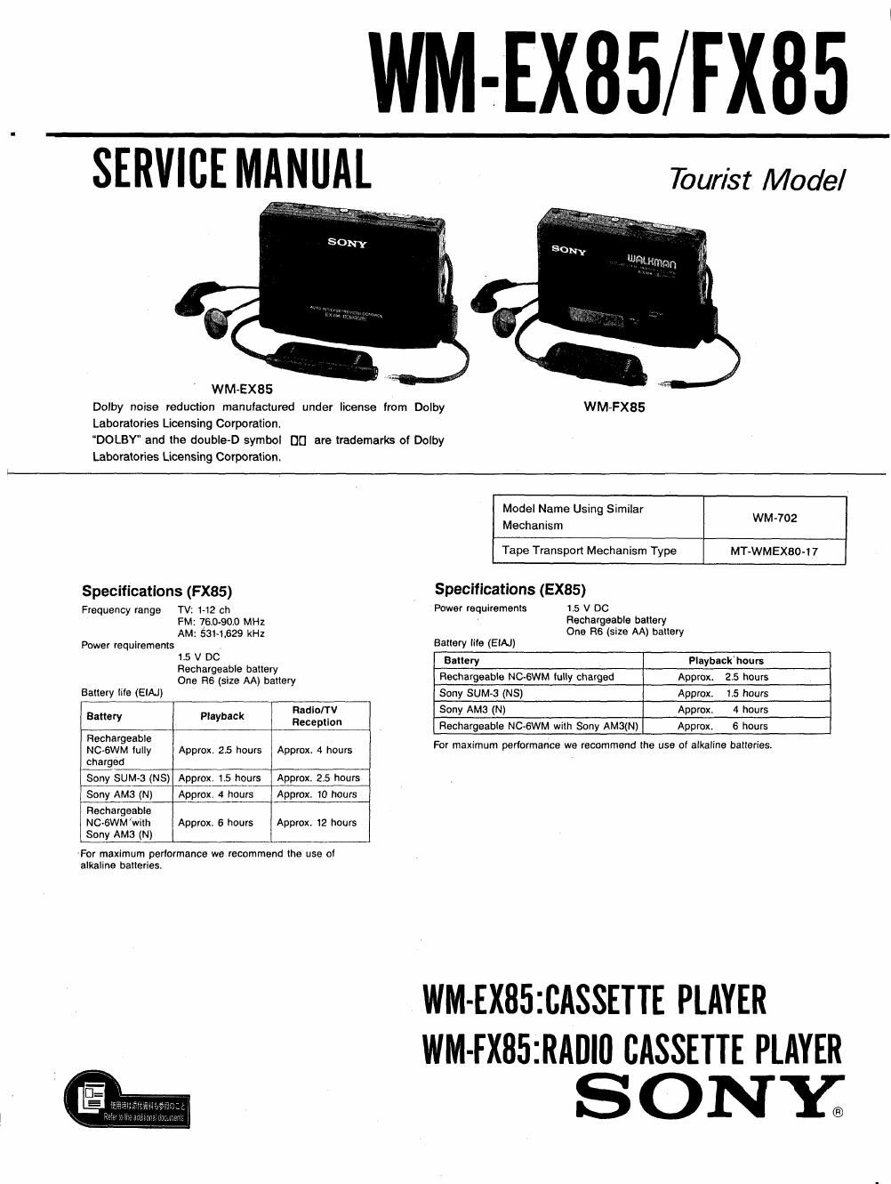
-EX85/EX85

SERVICE MANUAL Tourist Model

WM-EX85
Dolby noise reduction manulaclured under license from Dolby WM-FX85
Laboratories Licensing Corporation.

DOLBY and the double~D symbol DCI are trademarks of Dolby

Laboratories Lioensing Corporation.

Model Name Usin Similar
. 9 WM-702
Mechanism
Tape Transport Mechanism Type MT-WMEX80-17
Specifications (FX85) Specifications (EX85)
Frequency range TV 1-12 ch Power requiremenls 15 V DC
FM: 76.0-90.0 MHZ Rechargeable ballery
AM: 5314529 kHz One R6 (size AA) ballery
Power requirements , Battery tile (EIAJ)
:25 A DC bl n u 53 Playbackhours
ec or a e a er
One ngfsize AA) bayltery Rechargeable NC~6WM lully charged Approx 2.5 hours
Gallery lile (ElAJ) Sony SUM»3 (NS) Approx 1.5 hours
Battery Playback :INTV 5°"Y AMS (N) Approx 4 hours
99" Rechargeable NC-GWM wilh Sony AM3(N) Approx. 6 hours
Rechargeable . . .
NC-GWM lully Approx. 25 hours Approx. 4 hours For maximum performance we recommend [he use of alkaline batteries
charged

Sony SUMS (NS) Approx. 175 hours Approx, 25 hours
Sony AM3 (N) Approx. 4 hogs Approx. 10 hours

Rechargeable
NC-GWM/wixh Approx. 6 hours Approx 12 hours
Sony AM3 (N)

For maximum perlormanoe we recommend lhe use ol
alkaline batteries.

WM-EXBSICASSETTE PLAYER
WM-FX85IRADIO CASSETTE PLAYER

SONK

Page 2

WM-EX85/FX85


TABLE OF CONTENTS

Section ' Title Page
1. SERVICE NOTE-u 3
2. GENERAL. 4
3. ELECTRICALADJUSTMENT-m"-----~--~m~--~-~~m 5
4. IC TERMINAL DESCRIPTIOwa-u .......... 9
5. DIAGRAMS

o Cassette section Block Diagram-~ 11
0 Radio section Block Diagram .. 13
. semicondumors ........ ........... 15
0 Printed wiring Board - Cassette section ~ 15
- Schematic Diagram - Cassette section -~ 19
o Printed wiring Board - Radio section 23
- Schematic Diagram - Radio section - 25
6. EXPLODED VIEWS

(1) Ornament Block ............................. .. 27
(2) Main Boards Blockum- ' 28
(3) Mechanism Block (t)~~ , 29
(4) Mechanism Block (2)......... ................................ 3°
7. ELECTRICAL PARTS LIST- 31

SAFETY-RELATED COMPONENT WARNINGI!

COMPONENTS IDENTIFIED BV MARK A 0R DOTTED
LINE WITH MARK & ON THE SCHEMATIC DIAGRAMS
AND IN THE PARTS LIST ARE CRITICAL TO SAFE
OPERATION. REPLACE THESE COMPONENTS WITH
SONY PARTS WHOSE PART NUMBERS APPEAR AS
SHOWN IN THIS MANUAL OR IN SUPPLEMENTS PUB-
LISHED BY SONY.

About the headphones with remote controller

0 The supplied headphones with remote controller is to be used
only with this unit.

0 This unit cannot be operated with headphones supplied to
other models though they have the same plug as the
headphones supplied to this unit.

Also other models cannot be operated with the headphones
supplied to this unit. (But sound can be heard in either case.)

Notes on chip component replacement

0 Never reuse a disconnected chip component.

0 Notice that the minus side of a tantalum capacitor may be
damaged by heat.

Flexible Circuit Board Repairing

- Keep the temperature of the soldering iron around 270 °C
during repairing.

- Do not touch the soldering iron on the same conductor of the
circuit board (within 3 times).

0 Be careful not to apply force on the conductor when soldering
or unsoldering,

ATTENTION Au COMPOSANT AVANT RAPPORT
A LA SECURITE!

LES COMPOSANTS IDENTIFIES PAR UNE MAROUE A
sun LES DIAGRAMMES SCHEMATIOUES ET LA LISTE
DES PIECES SONT CRITIQUES POUR LA SECURITE
DE FONCTIONNEMENT. NE REMPLACER ces com-
POSANTS QUE PAR DES PIECES SONY DONT LES
NUMEROS SONT DONNES DANS c: MANUEL ou
OANS LES SUPPLEMENTS PUBLIES PAR SONY.