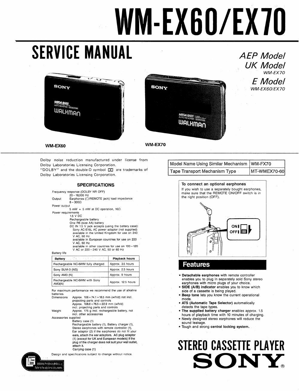
Sony wm ex 70 service manual
This is the 24 pages manual for sony wm ex 70 service manual.
Read or download the pdf for free. If you want to contribute, please upload pdfs to audioservicemanuals.wetransfer.com.
Extracted text from sony wm ex 70 service manual (Ocr-read)
Page 1
WM-EXBO/EX'III
SERVICE MANUAL
WM-EXGD WM-EX70
AEP Model
UK Model
WM-EX 70
E Model
WM-EX60/EX70
Dolby noise reduction manufactured under license from
Dolby Laboratories Licensing Corporation
"DOLBV" and the doubleD symbol DC are trademarks of
Dolby Laboratories Licensing Corporation.
SPECIFICATIONS
Frequency response (DOLBY NR OFF)
20 w 18.000 HZ
Output Earphones (fl/REMOTE lack) load impedance
8 - 300G
Power output
5 mW + 5 mW al DC operation. too
Power requiremens
15 v DC
nechargeaole battery
One as (size AA) battery
0c W 1.5 v iack accepts (using the battery case)
Sony AC-El5L AC power adaptor (not supplied)
available in the United Klngdom lot use on 240
V AC. 50 Hz
available in European countries lot use on 220
v Ac, so Hz ,
available In other countries 0! use on 100-120
V AC or 2207240 v Ac, so or 60 Hz
Battery lile
Battery Playback hours
Rechargeable NC-SWM tully charged Approx. 3.5 hours
Sony SUM-3 (NS) Approx 2.5 hours
Sony Atria (NJ Approx, 9 hours
Efficmhgggeabb NC-SWM with Sony Approx. 25 hours
For maximum perlormance we recommend the use OI alkaline
batteries.
Dimensions Approx. 106 x74.l x was mm (wlh/d) not incl.
projecting parts and controls
Approx. 1083 x765 x 229 mm (wlhld)
incl, ploiecllng parts and controls
Weight Approx 175 9 incl rechargeahle hallery. not
incl other accessories
Accessories supplied
Battery case (i)
Rechargeable battery (1). Battery charger (1)»
Stereo earphones with remote controller (1).
Ear adaptor (2) lI the earphones do not Iit your
ears. attach the ear adaptors. AC plug adaptor
(1) (except for UK and European models) N the
plug 01 the chataerdoes not suit your wall outlet,
attach It.
Carrying case (t)
Design and Specillcaltons sublecl to change wllhoui notice
Model Name Using Similar Mechanism WM-FX70
Tape Transport Mechanism Type MT-WMEX70-60
To connect an optlonal earphones
If you wish to use a separately nought earphones,
make sure that the REMOTE ON/OFF switch is m
the right position (OFF).
0 Detachable earphones with remote controller
enables you to plug in separately sold Sony stereo
earphones with micro plugs of your choice.
- SIDE (AlB) indicator enables you to know which
side of a cassette is being played.
0 Beep tone lets you know the current operational
mode.
- ATS (Automatic Tape Selector) automatically
detects the tape types
- The supplied battery charger enables approx. 1.5
hours of playback time with 10 minutes of charging.
. Newly designed stereo earphones will reduce the
sound leakage,
o Tough and strong central locking system.
STEREO CASSETTE PLAYER
S 0 NE
Page 2
WM-EX60/EX70
Section E? Page
Specifications ~~~~~~~~~~~~ 1
1 . SERVICING NOTE ..................... 2
2. GENERAL
Part5 Identification ........................ 3
Using on Extemal Power Sources ----------- 3
3. DISASSEMBLY
3-1. Panel Assy, Control Removal . - - - 4
3-2. Ornament Assy, Control Removal ----------- 4
4. ADJUSTMENTS
4-1. Mechanical Adjustments ................... 5
4-2. Electrical Adjustments 5
5. DIAGRAMS
5.1. Block Diagram ........................... 6
5-2 Printed Wiring Boards 9
5-3. Schematic Diagram ~~~~~~~~~~~~~ 13
s. EXPLODED VIEWS .................... 16
7. ELECTRICAL PARTS LIST ----------- 19
S OUARE WA VE
OSCILLA TOR
C-
-I SQUARE WAVE ~ - .
20 Hz gm
0 dB (1 V) w
TABLE OF CONTENTS
- MAIN Board (side A) -
FWD STOP *REV
\.
SECTION 1
SERVICING NOTE
This set detects reel rotation by PH701 (photo
sensor). Reel rotation cannot be detected when the
main board is removed, because PH701 is mounted on
the main board. As a result, the auto-off circuit and
tape end detection will misoperate. And, up and down
of head and power supply of playback circuit cannot
operate when the main board is removed, because S
703 (NR switch) is mounted to the main board (S703
is linked to on and off of the plunger solenoid.)
Therefore, operation check of the mechanism deck
and voltage check can be performed by the method
shown below.
FF/REW mode
1) Switch position 5703 : STOP (Center)
2) Apply the square wave signal to the PH701.
3) Press the « or » key.
PLAY mode
1) Switch position 8703 : STOP (Center)
2) Apply the square wave signal to the PH701.
3) Press the > key.
4) Turn on S703 a few seconds later.
- MAIN Board (side A) -