Sony wm ex 1 wm ex1hg

This is the 22 pages manual for sony wm ex 1 wm ex1hg.
Read or download the pdf for free. If you want to contribute, please upload pdfs to audioservicemanuals.wetransfer.com.

Page: 1 / 22
sony wm ex 1 wm ex1hg

Extracted text from sony wm ex 1 wm ex1hg (Ocr-read)


Page 1

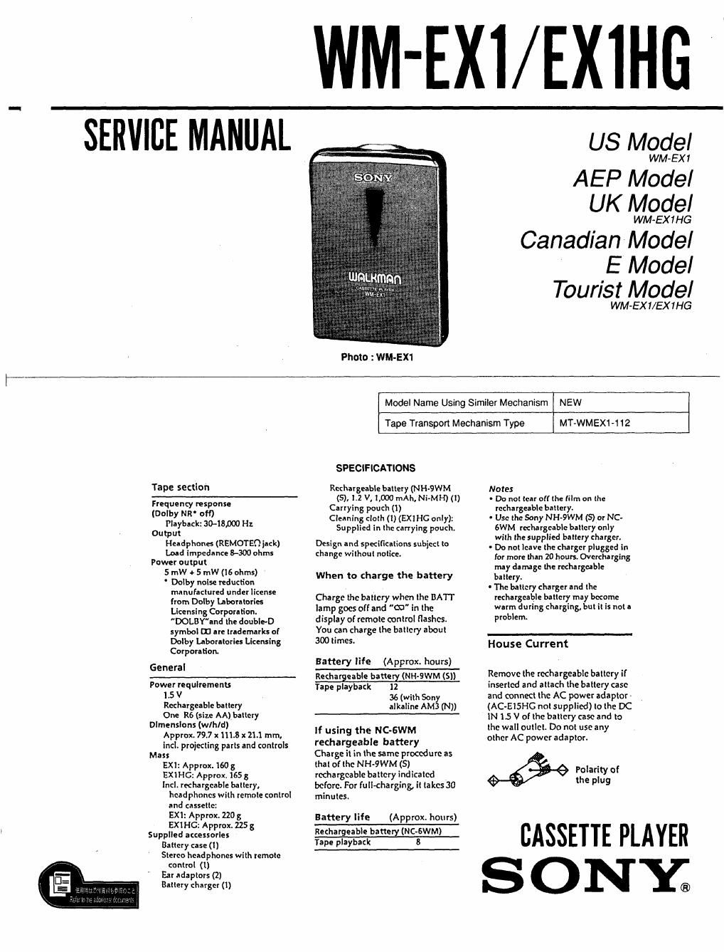
WM-EXI/EXIHG

SERVICE MANUAL

whammnn

Photo : WM-EX1

US Model

WM-EX 1

AEP Model
UK Model

WM-EX1HG

Canadian Model

E Model
Tourist Model

WM-EX1/EX1HG

Tape section

Frequency response
(Dolby NR off)
Playback: Ito-18,000 Hz
Output
Headphones (REMOTEQ jack)
Load Impedance 8-300 ohms
Power output

5 mW e 5 mW (16 ohms)

' Dolby noise reduction
manufactured under license
from Dolby Laboratories
Licensing Corporation.
DOLBYand the double-D
symbol on are trademarks of
Dolby Laboratories Licensing
Corporation

General

Power requlrements
1.5 V
Rechargeable battery
One R6 (size AA) battery
Dlmensluns (w/h/d)
Approx. 79.7 X1113 x 11.1 mm,
Incl. projecting parts and controls
Mass
EXl: Approx. 160 g
EXIHG: Approx. 165 3
Incl. rechargeable battery,
headphones with remnle control
and cassette:
EXI: Approx. 220 3
Ext HG: Approx. 225 g
Supplied accessories
Battery case (1)
Stereo headphones with remote
control (I)
Far adaptors (2)
Battery charger (1)

Model Name Using Similer Mechanism

NEW

Tape Transport Mechanism Type

MT-WMEXI-112

SPECIFICATIONS

Rechargeable battery (NHcSWM Notes
(5), 1.2 V, 1,000 mAh. Ni-MH) (I) ' Do not tear olfthe film on the
Carrying pouch (l) rechargeable battery.
Cleaning cloth (1) (EXIHC only): ' Use the Sony NH-9WM (5) at NC-
Supplied in the carrying pouch. 6WM rechargeable battery only
. . , , with the su lied batter char err
DeStgn and specifications sub)c than W'lhml "°" [or more than 20 hours. Overcha rging
may damage the rechargeable
when to charge the battery binary,
0 The battery charger and the
Charge the battery when the BA'IT rechargeable battery may become
lamp goes off and "m" in the warm during charging. but it is not a
display of remote control flashes. Pmblem

You an charge the battery about

300tim95~ House Current

Battery life (Approx. hours)

Rechargeable b'°!¥ (NH-QWM (5)) Remove the rechargeable battery if

739. playback 12 inserted and attach the battery case
36 (with Son and connect the AC power adaptor -
alkaline AM; (N)) (AC-EISHG not supplied) to the DC

1N15 V of the battery case and to

If using the Noswm the wall outlet. Do not use any

rechargeable battery

other AC power adaptor.

Charge it in the same procedure as

thal of the NH-9WM (S) _
rechargeable battery indicated 9% 31:3"?! 0
before. For full-charging, it takes 30 p 9

minutes.

Battery life (Approx. hours)

---~.__¢_ CASSETTE PLAYER
ONY;

Page 2

TABLE OF CONTENTS

Notes on chip component replacement

0 Never reuse a disconnected chip component

Notice that the minus side of a tantalum capacitor may be
damaged by heat

sggtlgn Titlg Raga
SECTION 1. GENERAL .l

SECTION 2. SERVICE NOTE .................................... 4

Flexible Circuit Board Repairing

SECTION 3. DI A M
' Keep the temperature of the soldering iron around 270 °C 8 SSE BLY

3-1. Cassette Lid Assembly..

.. 6

during repairing. 3'2i Case Assembly 6

0 Do not touch the soldering iron on the same conductor of the 3.3. Reel Ornament 6
circuit board (within 3 times) 3-4. Holder Assembly. 7

. Be careful not to apply force on the conductor when soldering 3-5. Main Board .. 7
or unsoldering. 3-6. Belt ............ , 7

SECTION 4. MECHANICAL ADJUSTMENTS i 8

SECTION 5. ELECTRICAL ADJUSTMENTS .............. 8

SECTION 6. DIAGRAMS

6.1. Semiconductor Lead Layouts

6-2. Printed Wiring Board .............

6'3. Schematic Diagram

6-4V Block Diagram .....

6-5. IC Pin Functions
lCGOl Motor Driver (L81679V) ............
IC701 System Controller (MB8913PFV)

SECTION 7. EXPLODED VIEWS
7-1. Ornament Section
7-2. Main Boards Section . ..
7-3. Mechanism Section (MT-WMEX1»112) ........................... 25

SECTION B. ELECTRICAL PARTS LIST .................... 26

SAFETV-RELATED COMPONENT WARNING I! ATTENTION AU COMPOSANT AYANT RAPPORT

COMPONENTS IDENTIFIED BY MARK A OR DOTTED

LINE WITH MARK A ON THE SCHEMATIC DIAGRAMS
AND IN THE PARTS LIST ARE CRITICAL T0 SAFE

OPERATION. REPLACE THESE COMPONENTS WITH
SONV PARTS WHOSE PART NUMBERS APPEAR AS
SHOWN IN THIS MANUAL OR IN SUPPLEMENTS
PUBLISHED BY SONV.

. A LA sEcuntTEit

LES composm'rs IDENTIFIES PAR UNE MAROUE A
sun LEs DIAGRAMMES scr-iEMATioUEs at LA LISTE
DES PIECES sour CRITIQUES POUR LA sEcunrrE
DE FONCTIONNEMENT. NE REMPLACER CES
composmrs oUE PAH oEs PIECES sour DONT
LEs NUMEROS som DONNES DANS cE MANUEL ou
oANs LEs SUPPLEMENTS PUBLIES PAH SONY.