Sony wm dd 9 service manual

This is the 19 pages manual for sony wm dd 9 service manual.
Read or download the pdf for free. If you want to contribute, please upload pdfs to audioservicemanuals.wetransfer.com.

Page: 1 / 19
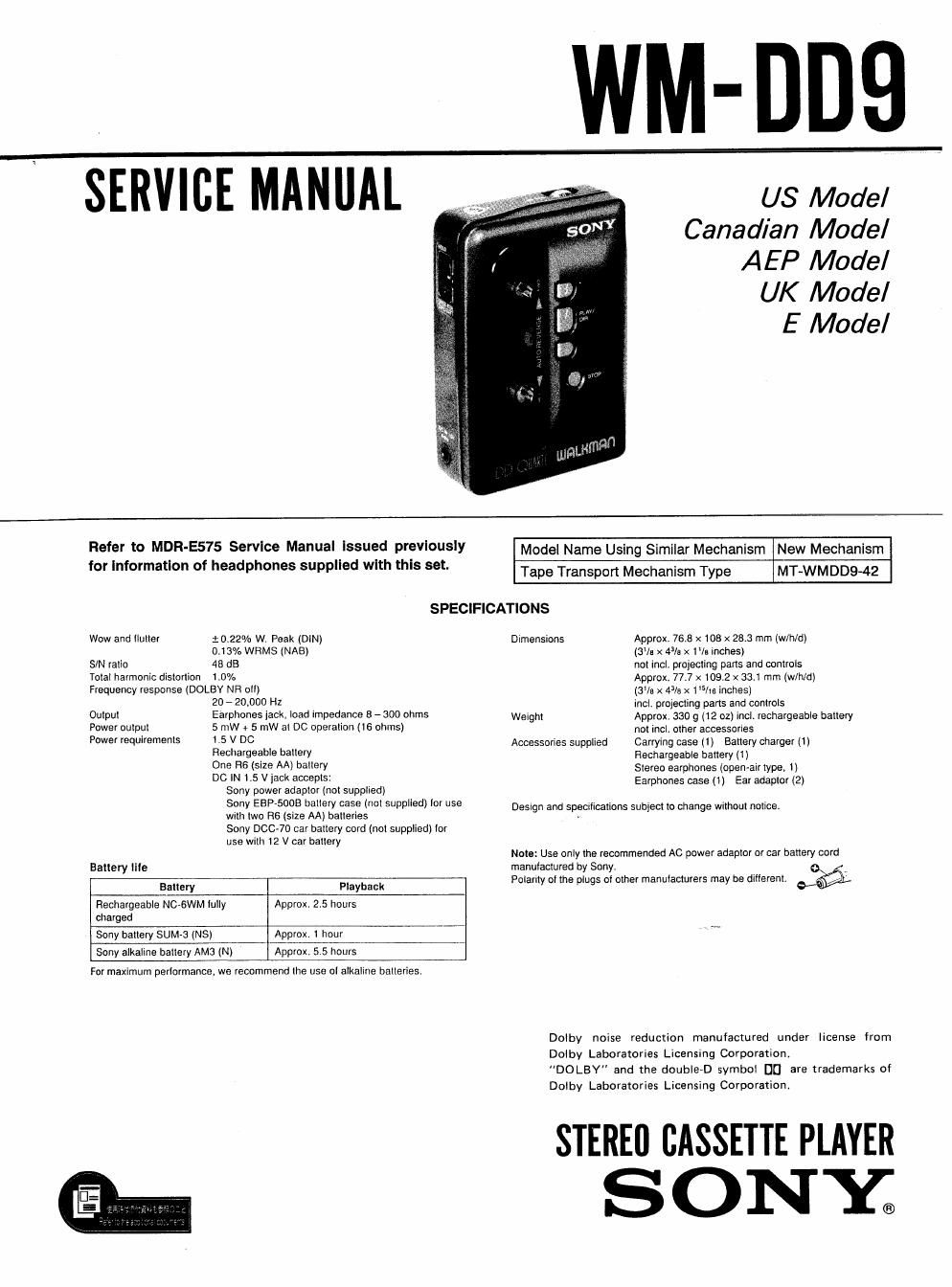
sony wm dd 9 service manual

Extracted text from sony wm dd 9 service manual (Ocr-read)


Page 1

SERVICE MANUAL

US Model
Canadian Model
AEP Model

UK Model

E Model

Refer to MDR-E575 Service Manual Issued previously

for Information of

Wow and iluller

S/N ratio
Total harmonic dislorlion

headphones supplied with this set.

Model Name Using Similar Mechanism New Mechanism

Tape Transport Mechanism Type MT-WMDD9-42
SPECIFICATIONS
$0.22% W. Peak (DIN) Dimensions Approx. 76.8 x 103 x 28.3 mm (w/h/d)

0.13% WRMS (NAB)
48 dB
1.0%

Frequency response (DOLBV NFI olll

Output
Power output
Power requiremenis

Baltery lile

20 - 20.000 Hz

Earphones lack. load impedance 8 - 300 ohms

5 mW 4 5 mW aI DC operalion (15 ohms)

1.5 V DC

Rechargeable ballery

One H6 (size AA) ballery

DO IN 1.5 V jack accepls:
Sony power adaptor (not supplied)
Sony ESP-5005 ballery case (nol supplied) lor use
With Iwo H6 (size AA) balleries
Sony 00070 car battery cord (n01 supplied) Ior
use with 12 V car batiery

Battery

Playback

charged

Rechargeable NCvBWM lully Approx. 25 hours

Sony ballery SUM-3 (NS)

Approx. 1 hour

Sony alkaline battery AMG (N) Approx. 5.5 hours

For maximum perlormance

, we recommend (he use oI alkaline balieries.

(3% x 4% x 1la inches)
not lncl. projecting parts and controls
Approx. 77.7 x 109.2 x 33.1 mm (will/d)
(31/9 x 4% x 1% inches)
incl. projecting pans and controls
Weighl Approx. 330 g (12 oz) Incl. rechargeable baltery
not incl. other accessories
Accessories supplled Carrying case (1) Battery charger (1)
Rechargeable battery (1)
Stereo earphones (open-alr type, 1i
Earphones case (1) Ear adaptor (2)

Design and spootiicaiions subject to change wrihoul notice.

Note: Use only the recommended AC power adaptor or car battery cord

manufactured by Sony, _
Polarity ol the plugs oi other manufacturers may be different. 6%

Dolby noise reduction manufactured under license from
Dolby Laboratories Licensing Corporation.
DOLBY and the double-D symbol DC] are trademarks of
Dolby LabOratories Licensing Corporation.

STEREII CASSETTE PLAYER
ONY;

Page 2

WM-DD9

SECTION 1
GENERAL

arts Identification

El DC iN t.5 V (external power input) jack

El REV/FWD (battery/tape transport direction) indicator

/
m I STOP button

ElEDE-El

- Two-motor Disc Drive mechanism and Quartz lock capstan servo assure
accurate and stable tape transport, greatly reducing wow and llutter.
One motor is provided tor the lorward direction and another for the reverse
direction Since the rotation at motors is controlled by the accurate lrequency oi
the quartz servo, distortion oi the sound caused by the unit being moved is
slight.

Drlve nysterrr or namut Drive system at wM-DDS
auto-reverse w-Ikmn

Flal rrtator Crystal osctllatnr

Sm
srghal

ti

FG
Motor tor th- 59"" Motor tar Ihe
lurwam drrecuo reverse direction
Capstarr tor the capstan tor the capstan tor the Cavslan tor "re
lorward direction reverse drmcwt lolwam direction reverse direction

El « tiast winding) button

E HOLD, OPEN FOR TAPE/BATT (battery) switch
Slide to HOLD to avoid an accidental operation. To open the cassette holder.
slide to OPEN FOR TAPE/BA'I'I', To open the battery companment lid, slide
again to OPEN FOR TAPE/BATE

El Cassette holder

El » (iast winding) button

[3 < > PLAY/DlFl (play/tape transport direction change) button

E DOLBY NR (Dolby noise reduction) (C/B/OFF) selector

MEGA BASS (MAX/MlD/NOHM) selector

{El TAPE (NORM/CrOz. METAL) selector

@ Hole tor attaching the carrying case

El VOL (volume) control

E (l (earphones) jack (stereo minijack)

El Battery compartment lid

IE] MODE (tape transport mode) selector

Notes on chip component replacement

Never reuse a disconnected chip component.
Notice that the minus side of a tantalum capacitor may
be damaged by heat

Flexlble Circult Board Repairing

0 Keep the temperature of the soldering iron around
270 "C during repairing,
Do not touch the soldering iron on the same conductor
of the circuit board (within 3 times).
Be careful not to apply force on the conductor when
soldering or unsoldering,