Sony wm bf 608 service manual

This is the 26 pages manual for sony wm bf 608 service manual.
Read or download the pdf for free. If you want to contribute, please upload pdfs to audioservicemanuals.wetransfer.com.

Page: 1 / 26
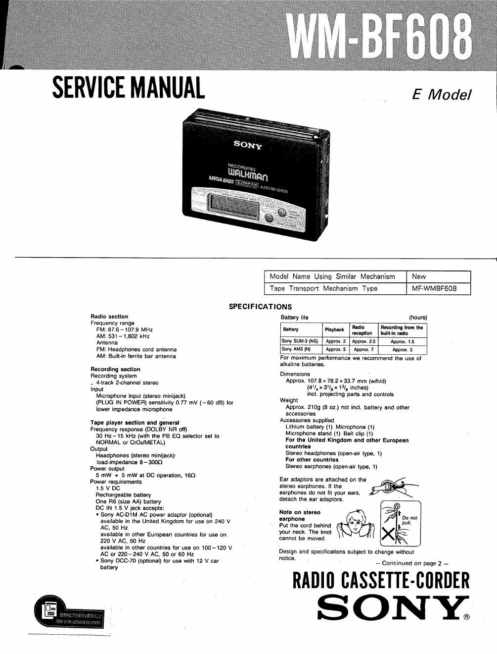
sony wm bf 608 service manual

Extracted text from sony wm bf 608 service manual (Ocr-read)


Page 1

SERVICE MANUAL

E Model

Model Name Using Similar Mechanism New
Tape Transport Mechanism Type MF-WMBFGOS
SPECIFICATIONS
Radio section Battery lite (hours)
Frequency range
FM; axe-107.9 MHz Battery Playback I WW "0'" l"
AM: 531-1 502 kHz '°°""°" "" "m
Anwnna sony sumo (NS) Approx, 2 Approx. 2.5 Approx. 15
FM: Headphones cord antenna Sony Auto (N) Approx. 5 Approx. 7 Approx. 3

AM: Built-in lerrlte bar antenna

Recording section

Recording system

. 4-track 2-channel stereo

Input
Microphone Input (stereo minijack)
(PLUG IN POWER) sensitivity 0.77 mV (-60 dB) (or
lower Impedance microphone

Tape player section and general
Frequency response (DOLBY NR aft)
30 Hz- 15 kHz (with the PB EO selector set to
NORMAL or Crop/METAL)
Output
Headphones (stereo miniiack)
loadiimpedance 6 - 3000
Power output
5 mW + 5 mW at DC operation, 160
Power requirements

1.5 V DC

Rechargeable battery

One R5 (size AA) battery

DO IN LS V jack accepts:

0 Sony AC-DlM AC power adaptor (optional)
available in the United Kingdom (or use on 240 V
AC, 50 H2
available in other European countries (or use on
220 V AC, 50 Hz
available in other countries (or use on 100-120 V
AC or 220-240 V AC, 50 or 60 Hz

- Sony 00070 (optional) lor use with 12 V car
battery

For maximum periormance we recommend the use at
alkaline batteries.

Dimensions
Approx. 107.8 x 73.2 x 38.7 mm (wlh/d)
(4I x 3'1, x 13/, inches)
incl. projecting parts and controls
Weight
Approx. 2109 (B oz.) not Incl. battery and other
accessories
Accessories supplied
Lithium battery (1) Microphone (1)
Microphone stand (I) Belt clip (1)
For the United Kingdom and other European
countries
Stereo headphones (open For other countries
Stereo earphones (open-air type, 1)

Ear adaptors are attached on the
stereo earphones, II the
earphones do not lit your ears.
detach the ear adaptors.

Note on stereo
earphone

Put the cord behind
your neck. The knot
cannot be moved.

Design and specifications subject to change without

notice,
-- Continued on page 2 -

RADIll CASSETTE-BORDER
SON Y.

Page 2

WM-BF608 1

Note
This appliance conforms with EEC directives 76/389
and 821499 regarding interlerence suppression.

Option-I accessories

AC power adaptor AC-DIM

Battery charger BC-7L, BC-7K
Rechargeable battery NC~6WM. NC-SWM
Car battery cord DCC~70

Lllttltun butlury CH 2016

Your dealer may not handle some oi the above listed
optional accessoriesPlease ask the dealer tor detailed
tntormation about the optional accessories available in
your country.

Note
It a car battery cord or an AC
power adaptor not manulactured

by Sony is used. a fuse must be 7
installed in the battery cord or
the adaptor, and the polarity at

the plug must be as illustrated.

TABLE OF CONTENTS

m M Egg
specifications .................................................................. 1
1. GENERAL ...... . ............... . ........... . .......... . .............. ..3
2 DISASSEMBLY ..... . ............ . ........... . ........... .. ........ 5

3. ADJUSTMENTS .

4. DIAGRAMS
44. Semiconductors Lead Layout -------------------- -----"9
4-2. Printed Wiring Board -Audio Section-"mu" 10

13

4-8. Schematic Diagram -Audio Section- -

44. Schematic Diagram -Radio Section- 16
4-5. Printed Wiring Board -Radio Section- - 19
45 [(3 Block Diagram ........ . ......... .......... .. ...... 22

5. EXPLODED VIEWS
5-1. Cabinet -----
5»2. Mechanism-
5-3. Mechanism-2'

6. ELECTRICAL PARTS LIST ----------------------------- 27

Flexible Circuit Board Repairing

I Keep the temperature of the soldering iron around
270°C during repairing.

0 Do not touch the soldering iron on the same conduc-
tor of the circuit board (within 3 times).

0 Be careful not to apply force on the conductor when
soldering or unsoldering.

Notes on chip component replacement

0 Never reuse a disconnected chip component.
0 Notice that the minus side of a tantalum capacitor
may be damaged by heat.