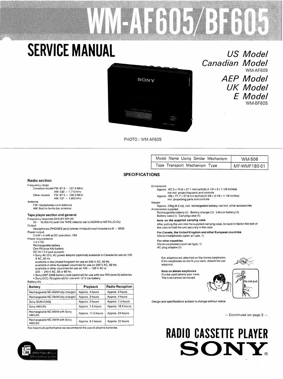
Sony wm bf 605 service manual
This is the 30 pages manual for sony wm bf 605 service manual.
Read or download the pdf for free. If you want to contribute, please upload pdfs to audioservicemanuals.wetransfer.com.
Extracted text from sony wm bf 605 service manual (Ocr-read)
Page 1
US Model
Canadian Model
WM-AF605
AEP Model
UK Model
E Model
WMaBF605
PHOTO : WM-AF605
Model Name Using Similar Mechanism WM~506
Tape Transpon Mechanism Type MF-WMF180-01
SPECIFICATIONS
Radio section
Frequency range Dlmenslons
Canaoran model FM: 87.9 - m7 9 MHz
AM: 530 A 1,710kHz
orher models m. 87 5 - r05 0 MHz
AM 531 - Leoz kHz
Anrenna
FM' Headphones cord anlenna
AM: Bulllrlrr lerlile bar anlenna
Taps player sectlon and general
Frequency response (DOLBY NR all)
Approx 107.5 x 74 s x 27 l mm (Wm/rho 1/4 x 3 x1 we Inches)
nal mcl prolecllng pans and conrrols
Approx roex 77.7 x 27 6 mm (wlhldj (4 are x a we x r we lnches)
lncl prolscllng pans and conlrols
Welghr
Approx 2309 (9.2 oz). lncl, rechargeable hallery. nor lncl. olhereceessories
Accessorres supplleo
Rechargeable halrery (r) Bauery charger (1 r Lilhlum oarrery (ll
Ballery case (r) Carrying case 11)
20 e 13,000 Hz rwnh me TAPE seleclor eel lo NORM or METAL/002) "e °" " 9 Wm
Oulpul
Aller purung lhe unll mlo lhe supphea carryrng case. be sure lo lesran lhe bell ol
Headphones (PHONES lack) (srereo minijack) load rmpaaance s - 3009 "'9 case In hold "'9 UH" securely in "I9 cassv
Power oulpul
5 mW + 5 mW 31 DC operallon. lsn
Power requrremehrs
For Cmadn. lhe Unlled Klngdom .na orher Europe-n counlrlu
srereo headphones [openralr lype, 1)
For other counlrles
r 5 v DC >
Rechargeable ballery Sleteo earphones (Open-all type. 1)
One Rs (slze AA) ballary AC plug adavlor 1!
DC IN 15 v lack accepts:
- Sony AC~DI L Ac power aoapror lephonal) ayauaole in Canada '07 use on I20
v AC. so Hz Ear adaprors are allacheo on me slereo earphones
avallable In rhe unrrea Kingdom ror use on 240 v AC. 50 Hz lr rhe earphones do nor In your ears, oeraoh rhe ear )%
avallabls in orher European oounrriee lor use on 220 v AC. so Hz aoaplors,
avallable In oIhel countries lo! use on IOO - 120 V AC 0'
220 7 240 V AC, 50 Dr 60 H1
More on aIereo earphones
. Sony ESP-sons oauery case (ophonan ror use wirh rwo R20 lslze D) oarrerlee Pur lhe cero behind your neolr,
- Sony DCC-7D (opllonal) lor use mm 12 v car oarrery The knor cannol be moved }
Balleryllle nonorpull,
Ballery Playback Hadlu Reception |
Rechargeable NC-6WM lully charged Approx. 4 hours Approx 6 hours
Rechargeable NC-5WM lully charged Approx. 3 hours Approx. 4 hours
Sony SUM~3 (NS) Approx 2 hours Approx. 7.5 hours Daergn and speclllcarlon: sublecl lo change wllhoul nollce
Sorry AMCl (N) Approx 7 5 hours Approx 15 5 hours
iffarmfeam "CGWM W'm 3" Approx 11 0 hours Approx. 24 hours _ Continued on page 2 __
iaghafieab'e NC'SWM w'm 5°"Y Approx 9 5 hours Approx. 22 hours
For maxlmum oerlormance we recommend lhe use 01 alkallne balleries
RADIfl CASSETTE PLAYER
SONx
Page 2
Not
This appliance conforms mm EEC uivmives 76/389 and 92/499 ramming ,TABLE OF CONTENTS
Inladorence auppressien.
Optlonnl Iccolsorlel . i
Battery case see-5003 Ac may adaptor AC-DIL 5.9% m Bags
Cur ballery cord DCC»70 Lithium battery CH-ZOG
Your dealer may not handle some al the above listed optional accessories. Please
asklttedealevtotdetailodintermaticn about the optional accossovieaavlilablo in Spec1ficauon................................................................... 1
your country.
We 1. GENERAL... ....... . ............................................... 3
It a car battery card or an AC Power adapter not manulacluved MI
by Sony is used, a luse musl be installed in me battery cord or
the adaptor, and [hepolarilyo'lheplug must be as illustrated 2 DISASSEMBLY . 5
3. ADJUSTMENTS .................. ..... ............ . ...... . ....... 6
4, DIAGRAMS
4-1. Printed Wiring Board -Audio Section-~-----~~---9
4-2. Schematic Diagram --Audio Section- 11
4-3. Schematic Diagram -Radio Section-u-"N-m" 14
44. Printed Wiring Board -Radio Section- 17
4-5. IC Block Diagram ~-
46. Semiconductors Lead Layout
..........,... 22
5. EXPLODED VIEWS
5.1. Cabinet ...... . .......................... . ........................ 23
52. Mechanism-l-~~~ 24
5-3. Mechanism-2mm" . 25
6. ELECTRICAL Mars 31- ...... 25
Flexible Circuit Board Repairing
0 Keep the temperature of the soldering iron around
270°C during repairing.
0 Do not touch the soldering iron on the same conduc-
tor of the circuit board (within 3 times).
0 Be careful not to apply force on the conductor when
soldering or unsoldering.
Notes on chip component replacement
0 Never reuse a disconnected chip component.
0 Notice that the minus side of a tantalum capacitor
may be damaged by heat.