Sony wm b 19 service manual

This is the 11 pages manual for sony wm b 19 service manual.
Read or download the pdf for free. If you want to contribute, please upload pdfs to audioservicemanuals.wetransfer.com.

Page: 1 / 11
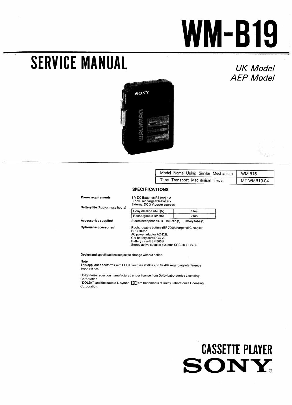
sony wm b 19 service manual

Extracted text from sony wm b 19 service manual (Ocr-read)


Page 1

WM-BIQ

SERVICE MANUAL UK Model

AEP Model

Model Name Using Similar Mechanism WM»BIS
Tape Transport Mechanism Type MT-WM81904

SPECIFICATIONS

Power requlrements 3 V DC Batteries 8601A) x 2
Esp-700 rechargeable batlery
Exlernal DC a V power sources

Battery IlIe (Approxumate hours)

Sony Alkaline AM3 (N) 6 first
Rechargeable BPJOO 2 hrs.
Accessorles supplied Stereo headphones (1) Beltclip (1) Battery lube (1)
Optional acccessarles Rechargeable baltery (BF-700)Icharger (BC-700) kit
BPC-700K'
AC power adaptor AODZL
Car battery cord D0070
Battery case ESP-5005

Stereo active speaker systems sns-ao. SRSASO

Design and specifications subject to change without notice.

Note
This appliance conIorms with EEC Dueclives 76/889 and 62/499 regarding interlerance
suppression.

Dolby noise reduclion manulacluled under license Irom Dolby Labaratories Licensmg
Corporalion

"DOLBY" and lhe double-D symbol DU are lrademarks ol Dolby Labotatovies Licensing
Corporation

CASSETTE PLAYER
ONY®

Page 2

WM-B1 9

SECTION 1
DISASSEMBLY

Location and shape of claws

The symbols (G-Q) show the order to uncouple the
linkage of the claw. and names of the parts.

Rear Cabinet Assy

Front Cabinet
Assy

Note: Follow the disassembly procedure the numerical order
given.

Tools: Precision Screwdrivers (6. width 0.8mm. 1.4mm, and
2.0mm)

Adhesive tape 1-22m
Wedge (hand made)

Material . .. soft plastic (such as PVC) etc.
Sizes are for the reference

3mm 9 0.3mm

[1] Cassette Holder Removal

Coil Spring

Open the cassette holder.

While pressing the edge of the cassette holder, pull up it
in order to take off the cassette holder.

Take off the end of coil spring with a precision screw-
driver (width : 0.8mm).

66

[2] Rear Cabinet Removal

0 Insert a precision screwdriver (width : 2.0mm) into the slit
of front cabinet, lift the front cabinet as shown in the
figure for making a clearance (0).

9 Insert a wedge in the clearance,

6 insert a precision screwdriver (width:2.0mm). and lift the
front cabinet so that the claw @ comes off.

0 In a similar way as procedure 6, uncouple the linkage oi
the claw O and (D.

_2_