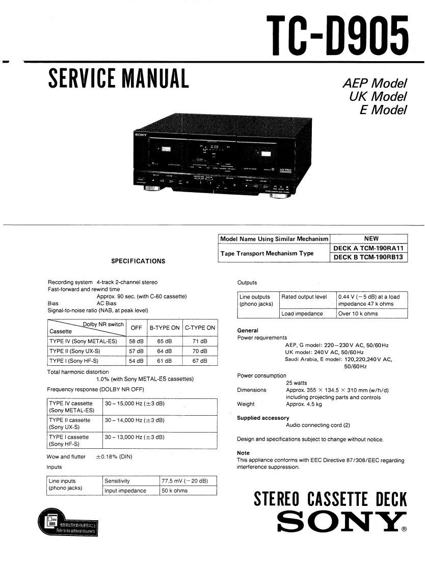
Sony TCD 905 Service Manual
This is the 29 pages manual for Sony TCD 905 Service Manual.
Read or download the pdf for free. If you want to contribute, please upload pdfs to audioservicemanuals.wetransfer.com.
Extracted text from Sony TCD 905 Service Manual (Ocr-read)
Page 1
TC-DQDS
SERVICE MANUAL
AEP Model
UK Model
E Model
NEW
DECK A TCM-190RA11
DECK B TCM-19ORB13
Model Name Using Similar Mechanism
Tape Transport Mechanism Type
SPEClFlCATIONS
Recording system 4-track 2-channel stereo Outputs
Fast-forward and rewind time
Approx. 90 sec. (with 0-60 cassette)
Bias AC Bias
Signal-tomoise ratio (NAB, at peak level)
0.44 V (- 5 dB) at a load
impedance 47 k ohms
Over 10 k ohms
Line outputs Rated output level
(phono jacks)
Load impedance
Why NR swm OFF 8~TVPE ON 07va ON
Cassette General
Power requrrements
TYPE |V (Sony METAL-ES) 58 dB 65 dB 71 dB AEP, G model: 220-230V AC, 50/60Hz
TYPE ll (Sony UX-S) 57 dB 64 dB 70 d8 UK model: 240V AC, 50/60Hz
TVPE ' (Sony HF-S) 54 dB 61 d8 67 d8 Saudi Arabia, E model: 120,220,240V AC,
50/60 Hz
Total harmonic distortion
~ Power consumption
9 .
1.0 /e (wrth Sony METAL ES cassettes) 25 watts
Frequency response (DOLBY NFl OFF) Dimensions Approx 355 X 134.5 X 310 mm (w/h/d)
including projecting parts and controls
Approx. 4.5 kg
TYPE lV cassette
(Sony METAL-ES)
30 ~15,000 Hz (i3 dB) Weight
Supplied accessory
TYPE ll cassette
30 - 14,000 Hz (:3 dB)
(phone jacks)
(Sony UX-S)
TYPE I cassette 30 ~13,000 HZ (:3 dB)
(Sony HF~S)
Wow and flutter :O.1B% (DIN)
Inputs
Line inputs Sensitivity 77.5 mV»(A20 dB)
input impedance
50 k ohms
Audio connecting cord (2)
Design and specifications subject to change without notice
Note
This appliance conforms with EEC Directive 87/308/EEC regarding
interference suppression,
STEREU CASSETTE DECK
SONY;
Page 2
TC-DSO5
TABLE OF CONTENTS
Section Title Page
Specifications ~~~~~~~~~~~~~~~~~~~~~~~~~~~~~~ 1
Servicing Note . . - . ~ 2
Model Identification ~~~~~~~~~~~~~~~~~~~~~~~~~~~~~ 2
SECTION 1. GENERAL
1-1. Location of Controls --------------------- 3
SECTION 2. DISASSEMBLY
21. Front Panel Assenbly ~~~~~~~~~~~~~~~~~~~~ 4
2-2. Mechanism Deck ~~~~~~~~~~~~~~~~~~~~~~~ 4
SECTION 3. ADJUSTMENTS
341. Mechanical Adjustments ------------------ 5
32. Electrical Adjustments ~~~~~~~~~~~~~~~~~~~~ 5
SECTION 4. DIAGRAMS
' 4-1. Circuit Board Location -------------------- 8
4-2 Semiconductor Lead Layouts ~~~~~~~~~~~~ 8
443. Printed Wiring Boards (Main Section) ----- 10
4-4. Schematic Diagram (Main Section) ~~~~~~~~~~ 15
4-5. Schematic Diagram (Panel Section) 19
4-6. Printed Wiring Boards (Panel Section) """ 23
SECTION 5. EXPLODED VIEWS
5-1. Chassis Section ~~~~~~~~~~~~~~~~~~~~ 25
5'2. Front Panel Section --------------------- 26
5-3i Mechanism Deck Section (1) ~~~~~~~~~~~~~~~ 27
5-4. Mechanism Deck Section (2) --------------- 28
SECTION 6. ELECTRICAL PARTS LIST -------- 29
MODEL IDENTIFICATION
-Specification Label-
SONYo MODEL N0, Tc-oeos
-
STEREO CASSETTE DECK
IV/ A
AEP, G model: AC: 220-230V ~ 50/60Hz
UK model: AC: 240V N 50/60Hz
Saudi Arabia, E model: AC: IZOV, 220V, 240V ~ 50/60Hz 25W
SERVICING NOTE
Flexible Circuit Board Repairing
0 Keep the temperature of the soldering iron around
270°C during repairing.
0 Do not touch the soldering iron on the same con-
ductor of the circuit board (within 3 times).
0 Be careful not to apply force on the conductor
when soldering or unsoldering.
Notes on chip component replacement
I Never reuse a disconnected chip component.
0 Notice that the minus side of a tantalum capacitor
may be damaged by heat.
SAFETY-RELATED COMPONENT WARNING
COMPONENTS IDENTIFIED BY MARK [A 0R DOTTED
LINE WITH MARK A ON THE SCHEMATIC DIAGRAMS
AND IN THE PARTS LIST ARE CRITICAL TO SAFE
OPERATION. REPLACE THESE COMPONENTS WITH
SONY PARTS WHOSE PART NUMBERS APPEAR AS
SHOWN IN THIS MANUAL OR IN SUPPLEMENTS PUB-
LISHED BY SONY.