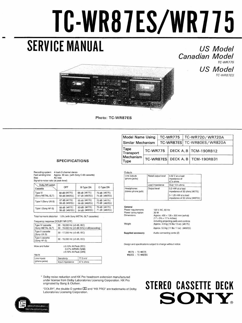
Sony tc wr 877 service manual
This is the 34 pages manual for sony tc wr 877 service manual.
Read or download the pdf for free. If you want to contribute, please upload pdfs to audioservicemanuals.wetransfer.com.
Extracted text from sony tc wr 877 service manual (Ocr-read)
Page 1
TC-WR87ES/WR715
SERVICE MANUAL us Model
Canadian Model
TC- WR 775
US Model
70 WR8 75$
Photo: TC-WR87ES
Model Name Using TC-WR775 TC-WR720/WR720A
Similar Mechanism TC-WR87ES TC-WRBOES/WR82OA
T
ape TC-WR775 DECK A, B TCM-190RB12
Tra nsport
Mechanism '
TC- R 7ES DECK A.B TCM-lQORBBl
SPECIFICATIONS Type W 8
Recording syslem thaw 2-channel s19rea Oulpuls
Freer winfling me Approx. 90 56¢ (wilh Sony 0'60 cassene) Line oulpms Rated oulpm level 0.32 v al a load
Bias AC bias (phono Jacksl impedance or
Slgnal-Io-nolss ralio (at peak level) 47 k ohms
Darby NR much Load impedance Over 10 k ohms
(3mm OFF ETYW 0 CTYFe 0 Headphones ompm level 0 2 mW al a load
h l
Type IV 53 63 mm 66 as (W775i 73 as M775) (stereo 9 one rack) Impedance o 32 ohms (W775 ;
(Sony METAL-8LT) 59 as (HR87ES l 57 dB (NR87ES) 74 no (names) 1H 25 "W 8 a '05
Impedance 0! 52 ohms (WINES)
V 57 4180:9175) 65 dB (""775) 72 dB (WR775)
Type " (SW UX 8 58 dB (mensi 66 aa (WWES) 73 dB (wens)
_ 55 a3 (W775) as as (WR77SI 70 dB (WR77Sl General
Type I (Sony HF 5) 55 dB (wuss) 54 dB (W753) 7( dB (W755, Power requiremems l20 v AC, (30 Hz
Power oonsurnplron 30 w
rolal harmonic disiomon l 0% (wan Sony METAL-8LT casselles) Dmensmm figpfggffifi $333123? mm (WM/d)
Frequency response (DOLBY NH OFF) lVICludirIg projecting pans and oonlrols
Type N cam 30 713,000 HZ (B (18, EC) Welghl Approx 4 9 kg (10le la ozl (W775)
(Sony METALVSLT) so , 15,000 Hz[13 dB ovum clairecorolng] Approx 5.3 kg (ll lbs ll ozl (mzzsi
35%??? 30 - l7rooo H1 (:3 dB, 150) Supplled accessory Audlo oonnecllng cords (2i
Type | oassene 30 _ (5,000 Hz (:3 as. lEC)
(Sony HF-S)
Design and specllrcalions sunrecl to change when: notice.
Wow and iluner : 013% w Peak (use)
0 07% WRMS (NABi
mum WPeak (DIN) lllR775 : TC-WRWS
lnpuis WR87ES : rcrwnms
Line inpurs Sensnivny 775 mV
(phone iackS) inpul impedance 47 k ohms
Dolby noise reduction and HX Pro headroom extension manufactured
under license from Dolby Laboratories Licensing Corporation HX Pro
originated by Bang &Oiulsen. STERE" CASSETTE DECK
DOLBY, the double-D symbol DU and HX PRO" are trademarks ol Dolby
Laboratories Licensing Corporaiion.
Page 2
TC-WR87ES/WR775
TABLE OF CONTENTS
L ctr/inn Til/u P0 6
SECTION I. GENERAL ---------------- 3
SECTION 2. DISASSEMBLY ------------- 4
SECTION 3. MECHANICAL ADJUSTMENTS ------- 7
SECTION 4. ELECTRICAL ADJUSTMENTS ------- 7
SECTION 5. DIAGRAMS
5*it Circuit Boards Location -------- 11
5-2. Semiconductor Lead Layouts ------ 12
5'3. Printed Wiring Boards- - - - - - - - -14
5-4. Schematic Diagram
Audio/Power Section-
5-5. Schematic Diagram
...... ....19
-System Control/FL/Panel Section-' - - -23
5-6. Schematic Diagram
wPanel Section- ............. 27
SECTION 6. EXPLODED VIEWS
6-1. Chassis Section- - - - - - ------ 30
6-2. Front Panel Section
5-3. Front Panel Section
6-4. Mechanism Section-I - - - - ------ 33
6-4. Mechanism Section-2 ---------- 34
FEATU RES
0 The Dolby HX PRO system which improves the
' A relay function for long recording and playback.
- Automatic tape type detection during playback and
° Auto-synchro dubbing at normal or high (double)
0 AMS and memory play functions which provide easy
access to desired selections.
elapsed recording or playback time for decks A and B.
SAFETY-RELATED COMPONENT WARNINGII
COMPONENTS IDENTIFIED BY MARK A OR DOTTED
ATTENTION AU COMPQSANT AYAN'I RAPPORT
LES COMPOSANTS IDENTIFIES PAR UNE MAROUE A
SAFETY CHECK-OUT
After correcting the original service problem,
Check the antenna terminals, metal trim, metallized
LEAKAGE TEST
The AC leakage from any exposed metal part to
I. A commercial leakage tester, such as the
manufacturers instructions to use these instru-
to
A battery-operated AC milliammeter. The Data
3. Measuring the voltage drop across a resistor by
To Exposed Metal
AC
0.75uF 'l: gram
LEI
'1 Earth Ground
Fig. A. Using an AC voltmeter to check AC leakage.
SECTION 7. ELECTRICAL PARTS LIST - - - ----- 35
linearity of a lanes high-range response during
recording.
recording,
speed.
0 An easy-to-read digital counter which shows the
LINE WITH MARK A ON THE SCHEMATIC DIAGRAMS
AND IN THE PARTS LIST ARE CRITICAL TO SAFE
OPERATION. REPLACE THESE COMPONENTS WITH
SONY PARTS WHOSE PART NUMBERS APPEAR AS
SHOWN IN THIS MANUAL OR IN SUPPLEMENTS PUB-
LISHED BY SONY.
A LA SECURITE!
sun LES DIAGRAMMES SCHEMATIOUES ET LA LISTE
DES PIECES SONT CRITIQUES POUR LA sécumré
DE FDNCTIONNEMENT. NE REMPLACER ces COM-
POSANTS our; PAR DES Puzces SONY DONT LES
NUMEROS SONT DONNES DANS ce MANUEL ou
DANS LES SUPPLEMENTS PUBLIES PAR soNv.
perform the following safety check before releasing
the set to the customer:
knobs, screws, and all other exposed metal parts for
AC leakage. Check leakage as described below.
earth ground and from all exposed metal parts to any
exposed metal part having a return to chassis, must
not exceed 0.5 mA (500 microampers). Leakage
current can be measured by any one of three
methods.
Simpson 229 or RCA WT-S40A. Follow the
ments.
Precision 245 digital multimeter is suitable for
this job.
means of a VOM or battery-operated AC volt-
meter. The limit" indication is 0.75V, so
analog meters must have an accurate low
voltage scale. The Simpson 250 and Sanwa
SH-63Trd are examples of a passive VOM that
is suitable. Nearly all battery operated digital
multimeter: that have a 2V AC range are
suitable. (See Fig. A)
Parr: on Set
voltmeter
ID. 75 V)
L- mi-