Sony tc wa 7 esa service manual

This is the 36 pages manual for sony tc wa 7 esa service manual.
Read or download the pdf for free. If you want to contribute, please upload pdfs to audioservicemanuals.wetransfer.com.

Page: 1 / 36
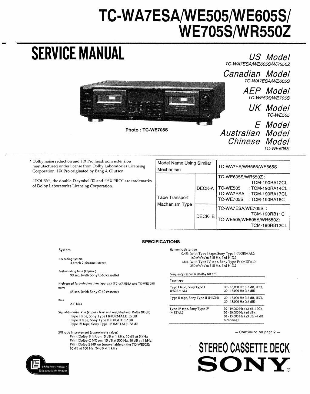
sony tc wa 7 esa service manual

Extracted text from sony tc wa 7 esa service manual (Ocr-read)


Page 2

Wow and flutter

IC~WA7ESAIWE7OSSIWE605SI
WR5502

TCAWESOS

20.!47c W. Peak (50
0.08% W. RMS (NAB)
20195!» Wu Peak (DIN)

20.I3% W. Itak (180
0.07% W. RMS (NAB)
x0.IR% W. Peak (DIN)

Variable pitch range (approx) (to-wens: and Tc-wEsos only)
-30 to 00%

Inputs

Line input: (phono iackx)
Sensitivity: 0.I6 V
Input impedance: 47 kilohms

Outputs

Line output; (phone iadtx)
Rated oulput level: 0.5 V at a load impedance of
47 kilohms
Load impedance: Over 10 kiluhm:

Headphone: (stereo phone jack)
Output level: 0.5 mW at a load impedance of
32 ohms

General

Power iequitemenls
Where purchased

US, Canadian.
Panama model

AEP. UK, Germant
Malaysia, Singapore.

Power requirements

[20V AC. 60Hz

- 230V AC. 50/6011:

Chinese model
AusIralian model 240V AC, SO/oOHz
E model llO/lZO/Z40V AC. SOIGUHZ

Pow" consumption
26W

Dimenrlonx (approx) (wilt/d)

UK, and Australian modcl 1
430 X l20 X 303 mm (w/h/d)
(I7 x4 lt x 12 inches)

EXCEPT UK, Australian model 1
430 X IZOX 290 mm (w/lI/d)
(l7 x4 V. X l I '/z illcllcs)
including projecting parts and controls

Mas: (approx)
4.2 kg (9 lbs 5 oz)

Supplied accessories
Auoio connecting cords (2 pltunt) plugs » 2 photto
plugs) (2)
Remote commander (RM-m0) (l) :
(WA7ESA ; Canadian model)

Design and specifications are subjecl to change without
notice.

TABLE OF CONTENTS
Section Title
Specifications .....................................
Safety Chock-out ......................
1. GENERAL
1.14 Identifying the pans ..........................

2. DISASSEMBLY
2-1, Front Panel Removal
2-2. Mechanism Deck -----
2-3. Capstan Motor, Reel Motor .
2-4. Head, Pinch Roller ~~~~~~~~~

3. ADJUSTMENTS
3-1. Mechanical Adjustments ~-
3-2. Electrical Adjustments

4. EXPLANATION OF IC TERMINALS ~~~~~~~~

5. DIAGRAMS
5.1. Block Diagram ..............................
52. Printed Wiring Boards (Main Section
5.3. Schematic Diagram (Main Section ~
5-4. Schematic Diagram (Panel Section
55. Schematic Diagram (Audio Section) .
5-6. Printed Wiring Boards (Audio Section)
5-7. Printed Wiring Boards (Dolby Section)
5-8. Schcmatic Diagram (Dolby Section)

6. EXPLODED VIEWS
6-1. Chassis Section -----
6-2. Front Panel Section
6-3. Mechanism Section 1
6-4. Mechanism Section 2...

7. ELECTRICAL PARTS LIST ....................

MODEL IDENTIFICATION
(Specification Label)

SONYa

STEREO CASSETTE DECK

WWW

MODEL NOt

US, Canadian, Panama model : AC 120V 60Hz
Australian model : AC 240V~50/60Hz
AEP, UK, Malaysia, Singapore,
Chinese, German model : AC 220- 230V~50l60Hz

E model : A01 20/220/240V~50/60Hz

................. 4

............... 11


............... 44

TC-WA7 ESA
TC-WE505

TC-WESOSS
TC-WE7OSS
TC-WRSSOZ